background image

JOHNSON CONTROLS

91

SECTION 5 - WIRING DIAGRAMS

FORM 102.20-OM2 

ISSUE DATE: 6/01/2015

5

X2

FU1

FU1

20

8/

23

0/

38

0/

46

0V

A

C

PH

A

SE

 IN

PU

T

FU2

CONNECTION DIAGRAMS

SEE TRANSFORMER

FOR PROPER

X1

CONNECTIONS

2L2

2L3

T1

L1

L3

L2

NOTE: CUSTOMER SUPPLIED

DISCONNECT MUST MEET
LOCAL CODES.

50

/6

H

Z

2

1

A

A

L2

L3

DISC

FU2

1

X2

CONNECTIONS

FOR PROPER

SEE TRANSFORMER

CONNECTION DIAGRAMS

2L2

X1

FU1

L2

FU1

T1

2L3

L3

C

ABC

AB

B

GFI

B

ABD

2KVA

AC

S

N

A

A

A

AB

B

L

SWITCH

LIGHT

SERVICE

2KVA

TRANSFORMER

TRANSFORMER

150VA OR 500VA

LINE

LOAD

PANEL

OPTION

WIRED IN YELLOW

OPTIONAL

M2

22

2

23

BC

2

SS1

XOO

B

A,B

AUTO

HAND

OFF

OOX

5

X2

14

8

M1

OR

OPTION

LTC

PANEL

OPTION

A,B

CONTROL POWER

6

B

LOW TEMP.
RESET

B

CONNECTING SAFETIES

REMOVE JUMPER WHEN

J

J

CLOCK

RUN/TIME

A

SAFETIES

FREEZESTAT

FIRESTAT

OL1

UP TO (4)

POWER

CONTROL

X2

A,B

100VA TRANS.

E

A

A

C

E

E

B

A

AB

2

1

3

7

6

8

1

2

9

1

3

4

6

7

1

2

1

2

3

8

X2

A,B

A

2

E

E

M2

10

2

XOO

A,B

DE

SS1

6

B

B

A

AUTO

OOX

CD

HAND

OFF

5

9

CLOCK

RUN/TIME

OL2

SUPPLY
FAN

FAN

RETURN

7

20

M1

21

 - TERMINAL POINT

 - REMOTE DEVICE (BY OTHERS)

NOTES:

M1

MOTOR

3PH

2T3

2T2

OL1

2T1

ALTERNATE OL1 - USED WITH CT1,2,3 WHEN MOTOR
                 FLA. IS GREATERTHAN 80 AMPS.

ALTERNATE OL1

OL1

CT3

CT2

CT1

M1

MOTOR

3PH

DISC2

FU3

M2

MOTOR

3PH

2T3

OL2

2T2

2T1

DISC3

FU4

THAN 60 AMP.

ARE GREATER

USED WHEN FUSES

SUPPLY FAN

RETURN FAN

SUPPLY FAN

ALTERNATE OL2 - USED WITH CT4,5,6 WHEN MOTOR

ALTERNATE OL2

                 FLA. IS GREATERTHAN 80 AMPS.

OL2

CT6

CT5

M1

CT4

MOTOR

3PH

SUPPLY FAN

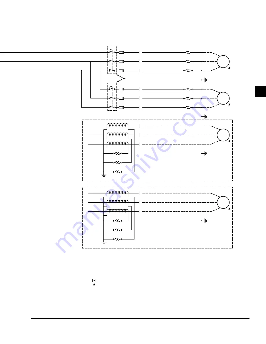
FIGURE 94

 - FULL VOLTAGE STARTER WITH SINGLE POINT POWER CONNECTION (204195) (CONT'D)

LD09684

Содержание AHU

Страница 1: ...ase Form 102 20 OM2 615 Issue Date June 1 2015 LD09624 OUTDOOR SOLUTION XT AHU INDOOR SOLUTION XT AHU YORK CUSTOM AHU LD13282 Renewal Parts With P N contact Balt Parts 800 932 1701 Manufactured or spe...

Страница 2: ...this document and any referenced materials This in dividual shall also be familiar with and comply with all applicable industry and governmental standards and regulations pertaining to the task in que...

Страница 3: ...er the equipment has been modified and if current literature is available from the owner of the equipment prior to performing any work on the unit CHANGE BARS Revisions made to this document are indic...

Страница 4: ...an with Service Disconnect only M SWSI PL Fan with Motor Starter N SWSI PL Fan with VFD P SWSI PL Fan Direct Drive without Motor Controller Q SWSI PL Fan Direct Drive with Service Disconnect Only R SW...

Страница 5: ...Wheel 29 Indirect Fired Gas Heat Start Up 34 Starting the Electric Heater 46 Operation 50 Test And Balance 50 Setting Limits 50 Checking Motors Belts and Sheaves 51 P Cone 51 SECTION 3 MAINTENANCE 53...

Страница 6: ...egment Cleaning 66 Tools Equipment and Materials 66 Cleaning Procedure 67 Condensate Drain Pan Trap and Line Cleaning 67 Tools Equipment and Materials 67 Schedule and Conditions 67 Cleaning Procedure...

Страница 7: ...s 80 Velocity 80 Static Pressure 81 Total Pressure 81 Requesting Assistance 81 Adjusting Removing and Installing Sheaves 82 Fixed Pitch Sheaves T B Woods With Sure Grip Bushings 82 Adjustable Pitch Sh...

Страница 8: ...URE 20 Metal Spacers on Solution XT Doors 29 FIGURE 21 Vertical Wheel for Indoor AHU 29 FIGURE 22 Horizontal Wheel for Outdoor AHU 30 FIGURE 23 Energy Recovery Wheel Pulley Side 31 FIGURE 24 Segment R...

Страница 9: ...e Segments 69 FIGURE 69 Diameter Seal Adjustment 69 FIGURE 70 Airxchange Energy Recovery Wheel With Bearing Support Beam Side 70 FIGURE 71 How to Measure 71 FIGURE 72 Disassembly 71 FIGURE 73 Assembly...

Страница 10: ...96 FIGURE 99 Transformer Wiring Diagram 97 FIGURE 100 UV Control Panel Wiring 8 amps 99 FIGURE 101 UV Control Panel Wiring greater than 8 amps 100 FIGURE 102 Gas Heat Single Phase 1500Va Transformer W...

Страница 11: ...C Copper Wire 47 TABLE 11 Minimum Maintenance Requirements According to ASHRAE 53 TABLE 12 Fan Bearing Re Lubrication Intervals for Ball Bearing Pillow Blocks 62 TABLE 13 Fan Bearing Lubrication Inte...

Страница 12: ...leaning 67 Freeze Protection 68 Drive Kit Inspection 55 Electric Heat Control Wiring 105 Energy Recovery Wheel Control Wiring 29 Start Up 32 External Lube Lines 61 Fan Assembly Pre Start Up Inspection...

Страница 13: ...rmation Johnson Controls warrants all equipment and materi als against defects in workmanship and materials for a period of 18 months from the date of shipment or 12 months from the date of start up w...

Страница 14: ...JOHNSON CONTROLS 14 FORM 102 20 OM2 ISSUE DATE 6 01 2015 SECTION 1 GENERAL INFORMATION AND SAFETY THIS PAGE INTENTIONALLY LEFT BLANK...

Страница 15: ...in Figure 2 on page 16 Never use silicone caulk sealant or caulk sealant containing silicone in or on any air handling equipment BEFORE START UP Perform a general inspection Identify and perform the...

Страница 16: ...t a satisfactory level compared to the value recorded prior to storage 3 Check the torque for bearings and locking collars as shown in Table 1 on page 16 Table 1 TORQUE FOR TIGHTENING SET SCREWS SETSC...

Страница 17: ...ating slightly deeper into the grooves of the sheaves Recheck the tension after one day and three days 3 Make sure the motor mounting bolts and adjust able motor base bolts are tight Checking Isolator...

Страница 18: ...emoving two nuts and one washer from each side Remove tubes from wire and discard wire STUD STUD TUBE TUBE 1 2 NUTS NUTS SHOULDER WASHER SHOULDER WASHER OPERATING POSITION SIDE VIEW EXPANDED ASSEMBLY...

Страница 19: ...ct 1 On three phase equipment reverse any two motor leads at the load side of the last starter component 2 On single phase equipment follow the wiring diagram on the motor housing or on the inside of...

Страница 20: ...damage the dampers Exception Actuators with over drive preset option Return air dampers may be closed for shipping Loosen the actuator or crank arm on the jackshaft open the dampers and retighten the...

Страница 21: ...TLI 1 40x40 39236 40 N A EPFN 1 245 3285 02 N A ATLI R 7x7 2200 70 0 4952 EPFN 2 245 3285 02 N A ATLI R 9x6 2759 60 0 5155 EPFN 3 245 3285 02 N A ATLI R 9x9 2805 50 0 4783 EPFN 1 270 3997 61 N A ATLI...

Страница 22: ...N A MPQN 3 122 944 92 N A MPQS 3 122 944 92 N A MPQN 1 150 1206 40 N A MPQS 1 150 1206 40 N A MPQN 2 150 1206 40 N A MPQS 2 150 1206 40 N A MPQN 3 150 1206 40 N A MPQS 3 150 1206 40 N A MPQN 1 165 15...

Страница 23: ...0 N A SF 2 245 3010 00 N A TABLE 2 AIR MEASURING DEVICE CONNECTIONS CONT D Air Measuring at the Fan Inlets COMETER is a probe attached to the fan bearing support on Comefri Forward Curve fans from siz...

Страница 24: ...r Airflow Measurement Performance Damper Operation The AMS 60 airflow monitoring damper design incor porates a low leakage control damper with stationary vertical air monitoring blades and air straigh...

Страница 25: ...omizer and mixing box sections will utilize an integral rain resistant airflow sensing louver damper combination with operation and set up similar to the AMS 60 The indoor and outdoor AHU designs have...

Страница 26: ...flow moni toring station is 300 FPM for the indoor AHU and 345 FPM for the outdoor AHU Factory Mounted Control Option The AMS 60 airflow monitoring station may be or dered with or without Factory moun...

Страница 27: ...Seal for Airflow Measurement Performance If airflow station is internally mounted inside air han dling unit and incorporates a control damper the con trol damper must comply with leakage rates of dam...

Страница 28: ...ly Man ual Form 102 20 N3 to install the Johnson Controls actuators Damper Blade Orientation Use the following instructions to orient the damper blades Return Air and Mixing Dampers 1 Position the bla...

Страница 29: ...tart up Failure to properly set up the VFD before applying power to the motor will void the fan and motor warranty Figure 19 EXAMPLE OF SWEEP BALANCE RESULTS LABEL ON FAN HOUSING LD16564 Check Doors A...

Страница 30: ...Return Air Return Air R A Damper O A Bypass E A Bypass O A Damper Exhaust Fan Exhaust Fan When the AHU is operating normally or temporarily the energy recovery wheel must rotate to prevent clogging M...

Страница 31: ...the AHU and confirm the wheel rotation The wheel rotates clockwise from the pulley side 4 If the wheel has difficulty starting turn the power off and inspect it for excessive interference be tween the...

Страница 32: ...ed If the eye bolts need to be removed bolts or plugs should replace them in order to avoid any air leak age from these holes required with top bottom and side galvanized plate option only 3 Grease bo...

Страница 33: ...e seal tek screws Then move the seal away from the wheel surface until no more rubbing is noticed A typical large diameter wheel will have a flat ness variation of 1 16 from the high to the low point...

Страница 34: ...prior to start up This gas burner has been carefully inspected and tested at the factory however different conditions at the job site including controls that have been added at the time of installati...

Страница 35: ...ontrol Signal Generator 0 to 20 mA Altek 234 or 334A For 2 to 10 VDC signal add 500 ohms in series with signal generator Magnehelic Gauge 0 15 in WC and 0 to 3 lb Dw yer series 2000 or Monometer Dwyer...

Страница 36: ...rate without leaks 7 The flue stack damper is located at the discharge of the ID blower and was closed for shipping Re lease the locking mechanism and set the damper to match the position indicated by...

Страница 37: ...st verify the incoming gas pressure A minimum pressure is listed on the burner test report The maximum pressure is listed as well 2 Open the manual gas valves on gas supply and pilot line 3 Initiate a...

Страница 38: ...15 Efficiency at high fire is pre determined but may be checked by flue gas analysis at the entrance to the ID Blower Housing Test Port At high fire the CO2 should be between 8 1 2 and 10 the 02 shou...

Страница 39: ...HSG AHU VOLTAGE CONTROL VOLTAGE T STAT VOLT AGE BURNER MOD CONTROL A 15 150 A ANSI 3 3 1 L Left G Galvanized A 120 1 60 A 24 A 2 10 VDC B 20 200 U UL 10 10 1 R Right S Stainless B 200 or 208 3 60 B 12...

Страница 40: ...5 N A 5 N A 5 N A 18 N A 18 050 N A 14 N A 27 N A 27 N A 27 N A 27 N A 27 050 N A 5 NA 5 N A 5 N A 5 N A 18 N A 18 060 N A 27 N A 27 N A 27 N A 27 N A 27 N A 27 060 N A 6 NA 6 N A 6 NA 6 N A 19 N A 19...

Страница 41: ...5 N A 5 N A 5 N A 18 N A 18 050 N A 14 N A 27 N A 27 N A 27 N A 27 N A 27 050 N A 5 NA 5 N A 5 N A 5 N A 18 N A 18 060 N A 27 N A 27 N A 27 N A 27 N A 27 N A 27 060 N A 6 NA 6 N A 6 NA 6 N A 19 N A 1...

Страница 42: ...1 00 NA 1 00 NA 1 00 050 NA 1 00 NA 1 00 NA 1 00 NA 1 00 NA 1 00 NA 1 00 060 NA 1 00 NA 1 00 NA 1 00 NA 1 00 NA 1 00 NA 1 00 075 NA 1 00 NA 1 00 NA 1 00 NA 1 00 NA 1 25 NA 1 25 085 NA 1 00 NA 1 00 NA...

Страница 43: ...F PANEL ROOF PEAK PIPE CHASE ID FAN TRANSITION PIECE 6 in L SLIP JOINT 42 in L VSI PIPE NOT INSULATED STORM COLLAR SUPPORT ASSEMBLY FLUE CAP 44 40 TYP 36 00 MIN 1 60 5 50 12 EXT 7 75 0 43 in CLEARANCE...

Страница 44: ...44 FORM 102 20 OM2 ISSUE DATE 6 01 2015 SECTION 2 START UP AND OPERATION Connect Signal Generator here for test and start up Jumper may be required here for test and start up Figure 36 TYPICAL WIRING...

Страница 45: ...00 57 64 0 86 7 500 53 60 0 98 8 000 50 56 1 1 8 500 47 53 1 23 9 000 46 50 1 38 10 725 38 8 43 2 2 DF 60 DF 75 6 000 91 0 44 6 500 84 0 52 7 000 78 0 6 7 500 73 91 0 68 8 000 68 85 0 78 9 000 61 76 0...

Страница 46: ...inimum velocity must be provided at all points over the heater face area Failure to meet this requirement may result in se rious damage or nuisance thermal cutout tripping 2 The maximum air inlet temp...

Страница 47: ...tors in a raceway derate these amperages per NEC Table 310 15 b 2 a Table 10 MAXIMUM CURRENT FOR 75 C COP PER WIRE AMPS Wire Size Awg MCM AMPS Wire Size Awg MCM AMPS Wire Size Awg MCM 125 100 125 100...

Страница 48: ...s injury or death Use the following instructions to start up the electrical heater 1 Check all electrical connections in the heater in cluding both field and factory installed connec tions for tightne...

Страница 49: ...GATIVE PRESSURE AIR DRAWN THROUGH HEATER BLOWER BLOWER HEATER HEATER AIRFLOW PICK UP T UBE TOWARDS BLOWER ATTACHED TO HIGH PORT OF AIRFLOW SWITCH PICK UP TUBE TOWARDS BLOWER ATTACHED TO LOW PORT OF AI...

Страница 50: ...s resulting in personal injury or death Never use silicone caulk sealant or caulk sealant containing silicone in or on solu tion air handling equipment Test And Balance Air Balance System air balance...

Страница 51: ...is performed It is not un usual for an adjustable sheave to create damaging vi bration in the fan assembly Replacing Sheaves Use the following instructions to replace the sheaves 1 Measure the outside...

Страница 52: ...JOHNSON CONTROLS 52 FORM 102 20 OM2 ISSUE DATE 6 01 2015 SECTION 2 START UP AND OPERATION THIS PAGE INTENTIONALLY LEFT BLANK...

Страница 53: ...tegrity Clean when necessary X Verify sensors used for dynamic minimum outdoor air con trol accuracy and recalibrate or replace as necessary X Measure the minimum quantity of outdoor air in the AHUs e...

Страница 54: ...ced use the instructions later in this section Hoods and Louvers Inspect the air hoods and louvers for damage and de bris Remove debris as needed Bird Screens Bird screens are an integral part of hood...

Страница 55: ...y de sign of each fan assembly is listed on the tag affixed to the fan housing near the belts as shown in Figure 43 on page 55 Figure 43 TYPICAL DRIVE KIT DATA TAG LD16565 OPERATING ADJUSTABLE MOTOR B...

Страница 56: ...ES 1 THE SHEAVES SHOULD BE CENTERED ON THE SHAFT S KEYWAY SHEAVE CAN BE CLOSER TO THE BEARING AS LONG AS THE SHEAVES HUB IS ABLE TO FULLY ENGAGE WITH THE KEY 2 CHECK FOR PARALLEL MISALIGNMENT BY PLACI...

Страница 57: ...rom the bottom of the small O ring on the deflection force scale 6 Compare the force you have applied with the value given on the drive kit data tag as shown in Figure 43 on page 55 Never use excessiv...

Страница 58: ...STRAIGHT EDGE LD09646 Straight Edge Touching Sheaves At Points Indicated By Arrows ALIGNMENT USING STRAIGHT EDGE Figure 49 ALIGNMENT USING STRING LD09646a Cord Touching Sheaves At Points Indicated By...

Страница 59: ...nting hardware on the opposite drive side is secure 9 Continue to tighten the belt s using the drive side the adjusting screws 10 If the sheaves are still misaligned as shown in Fig ure 51 on page 59...

Страница 60: ...to be relubricated in the field as shown in Figure 54 on page 60 Standard Pillow Block as shown in Figure 55 on page 60 Split Pillow Block as shown in Figure 57 on page 61 1 Seal 4 2 Housing Cap 3 Ca...

Страница 61: ...f any chemical impurities such as free acid or free alkali dust rust metal particles or abrasives This light viscosity low torque grease is rust inhibited and water resistant and has a temperature ran...

Страница 62: ...24 7 OPERATION SPEED RPM 500 750 1000 15000 2000 2500 3000 3500 4000 SHAFT DIAMETER IN 1 2 to 1 11 16 6 4 4 4 3 2 2 1 1 1 15 16 to 2 7 16 4 4 3 2 1 1 2 11 16 to 2 15 16 4 4 2 1 3 7 16 to 3 15 16 4 2...

Страница 63: ...h as Polyrex EM Exxon Mobile for all T frame motors 2 Maximum operating temperature for standard motors is 166 F 75 C 3 Recommended lubrication intervals are shown in Table 16 on page 64 Refer to all...

Страница 64: ...CORROSION BALL THRUST ROLLER EXTREME 50 C or CLASS H INSULATION SEVERE DIRT ABRASIVE DUST ALL BEARINGS LOW TEMPERATURE 30 C CORROSION Special high temperature grease is recommended Note that high temp...

Страница 65: ...G V RAY AND V MAX GRID LAMPS LD16552 Figure 64 V MAX GRID LAMPS V_Max MAINTAINING AND REPLACING FILTER SEGMENTS A list of filter part numbers sizes and quantities are shown on a label located on each...

Страница 66: ...LE FILTERS LD09651 Filter Filter Frame End Cover Rigid Filter Pre Filters Figure 67 INSTALLING SIDE LOAD FILTERS LD09652 Filter Frame End Cover ECONOMIZER SEGMENT DAMPERS Prior to occupancy test venti...

Страница 67: ...ssure may result in fin surface damage Direct the water straight at the openings between the fins and never at an angle which may bend the fins against one another This process will wash away surface...

Страница 68: ...n must be circulated During winter operation and shutdowns such as power failure night shutdown and weekend shut down the controls must be installed so the valves will go to the full heat position and...

Страница 69: ...g in the wheel will be dried out by the airflow Figure 68 RINSE SEGMENTS LD09659 Some staining of the desiccant may re main and is not harmful to performance Do not use acid based cleaners aromatic so...

Страница 70: ...ES Cleaning the Wheel The wheel should be protected by an ASHRAE 30 filter to keep dust and dirt from the heat transfer sur face If the wheel becomes dirty it may be cleaned by blowing out the unit wi...

Страница 71: ...r every 20 of C and D sections This gives the correct installed belt length and will ensure optimum belt ten sion when running LD17099 Figure 71 HOW TO MEASURE Every tenth link is designated with an a...

Страница 72: ...intenance of the drive systems and main bearings The key is to make sure the wheel is always turning in order to uti lize the counter flow airstreams and the purge sector to keep the media clean Over...

Страница 73: ...10 years depending on the environmen tal condition INNERGY TECH Cleaning the Wheel In most applications it is not necessary to clean the media of the wheel because the wheel rotates Incom ing and outg...

Страница 74: ...ks If the belt needs re placement contact Innergy tech for a new belt Innergy tech will need the serial number and the size of the wheel The belt is directional it must be installed with the direction...

Страница 75: ...ck flushing each line gently with compressed air may help to blowout debris in the line and pressure pickup holes It is helpful to keep the inside surface of the cone clean especially in a one inch ra...

Страница 76: ...JOHNSON CONTROLS 76 FORM 102 20 OM2 ISSUE DATE 6 01 2015 SECTION 3 MAINTENANCE Figure 79 MAINTENANCE REQUIREMENTS...

Страница 77: ...NETRATE WIREWAYS in any manner These sheet metal channels which run along the top panel contain electrical wires and connections Elec trical shock and or damage to the AHU may result Never use silicon...

Страница 78: ...ry slight compared to the positive circulation required in an air conditioning system To accomplish this air move ment a fan performs two functions Produce sufficient pressure or head to accelerate th...

Страница 79: ...r condition ing work and like the manometer is available in a va riety of ranges A minehelic guage is only two in in di ameter and has a limited scale A magnehelic gauge is four in in diameter and has...

Страница 80: ...80 LD27928b Figure 86 SLACK TUBE MANOMETER DUCT PRESSURES Velocity When air moves at a given velocity V in FPM in a duct it creates a pressure corresponding to the veloc ity which is a measure of the...

Страница 81: ...lways positive SP when it is above atmospheric pressure will be positive but when below atmospheric pressure it will be negative The discharge side of a fan in an air system will read a positive press...

Страница 82: ...wn KEYWAY GROOVE WEB LOCKWASHERS CAPS SCREWS TAPERED BORE SHEAVE BUSHING LD09664 Figure 88 INSERTING CAP SCREWS 3 Separate the sheave from the bushing 4 Standard Mounted Thread the cap screws into the...

Страница 83: ...h to prevent the bushing from sliding onto the shaft a Pull the sheave up onto the bushing align the drilled holes in the bushing flange with the tapped holes in the sheave b Loosely thread the cap sc...

Страница 84: ...t Place the fan and motor sheaves on their respective shafts far enough to have the shaft exposed past its chamfer which will facilitate proper alignment later in the process 3 The central sleeve of t...

Страница 85: ...the mounting setscrew in the central sleeve over the keyway 3 Inspect the shaft and key for any nicks and burrs Remove same and clean shaft 4 Insert the key into the keyway 5 Slide the new sheave ont...

Страница 86: ...14 To prevent damage to the central sleeve threads the set screws MUST be over one of the flat areas of the central sleeve If the flange is not properly locked the sheave will fail rapidly 15 Install...

Страница 87: ...void the manu facturer s warranty and cause serious damage to property or injury to persons Rotating parts and electrical shock haz ards exist Follow the lates lock out and tag out procedures for the...

Страница 88: ...XOO OOX OFF HAND AUTO CONTROL POWER OPTION PANEL OR LTC OPTION 2 CONTROL POWER UP TO 4 100VA TRANS LOW TEMP RESET PDTB 1 PANEL OPTIONAL 3 PHASE INPUT L1 208 230 380 460VAC DISCONNECT OPTIONAL LOCAL C...

Страница 89: ...OM2 ISSUE DATE 6 01 2015 5 M1 MOTOR 3PH T3 T2 OL1 T1 ALTERNATE OL1 USED WITH CT1 2 3 WHEN MOTOR FLA IS GREATERTHAN 80 AMPS TERMINAL POINT REMOTE DEVICE BY OTHERS ALTERNATE OL1 OL1 CT3 CT2 CT1 M1 MOTO...

Страница 90: ...SWITCH LIGHT SERVICE 2KVA TRANSFORMER TRANSFORMER 150VA OR 500VA LINE LOAD PANEL OPTION WIRED IN YELLOW OPTIONAL M2 22 2 23 BC 2 SS1 XOO B A B AUTO HAND OFF OOX 5 X2 14 8 M1 OR OPTION LTC PANEL OPTIO...

Страница 91: ...LA IS GREATERTHAN 80 AMPS ALTERNATE OL1 OL1 CT3 CT2 CT1 M1 MOTOR 3PH DISC2 FU3 M2 MOTOR 3PH 2T3 OL2 2T2 2T1 DISC3 FU4 THAN 60 AMP ARE GREATER USED WHEN FUSES SUPPLY FAN RETURN FAN SUPPLY FAN ALTERNATE...

Страница 92: ...D C LOCATED IN MB FM R SIGNAL COM DAMPER INTERLOCK RELAY CIRCUIT A1 A2 3C 6C LD12500 INSTALLING KIT IF APPLICABLE 1 This kit will be required for some of Johnson FEC control standards 100 outside air...

Страница 93: ...JOHNSON CONTROLS 93 SECTION 5 WIRING DIAGRAMS FORM 102 20 OM2 ISSUE DATE 6 01 2015 5 Figure 96 SOLUTION XT TERMINATION CHART INSIDE ENCLOSURE DOOR Termination Chart...

Страница 94: ...JOHNSON CONTROLS 94 FORM 102 20 OM2 ISSUE DATE 6 01 2015 SECTION 5 WIRING DIAGRAMS LD17195 Figure 97 TYPICAL FPC WIRING DIAGRAM...

Страница 95: ...JOHNSON CONTROLS 95 SECTION 5 WIRING DIAGRAMS FORM 102 20 OM2 ISSUE DATE 6 01 2015 5 LD17196 FIGURE 97 TYPICAL FPC WIRING DIAGRAM CONT D...

Страница 96: ...5 SECTION 5 WIRING DIAGRAMS LOAD WHITE HOT LINE WHITE HOT X2 B N L A L B L A S 1 B N L S 1 X2 1 B 1 A 2L3 2L2 X2 A 1 A S L B N GND GRD FU1 FU2 X1 FU1 X1 X2 A X2 B 2L3 2L2 GND TO TRANSFORMER Figure 98...

Страница 97: ...E 6 01 2015 5 SWITCH B L AB B B LOAD GFI A S SERVICE LIGHT A A A N A LINE X1 FU2 2L2 FU1 L2 1 ABD 6 C AC E 3 1 ABC SEE TRANSFORMER TRANSFORMER FOR PROPER CONNECTIONS CONNECTION DIAGRAMS AB 2KVA T1 2KV...

Страница 98: ...JOHNSON CONTROLS 98 FORM 102 20 OM2 ISSUE DATE 6 01 2015 SECTION 5 WIRING DIAGRAMS THIS PAGE INTENTIONALLY LEFT BLANK...

Страница 99: ...JOHNSON CONTROLS 99 SECTION 5 WIRING DIAGRAMS FORM 102 20 OM2 ISSUE DATE 6 01 2015 5 Figure 100 UV CONTROL PANEL WIRING 8 AMPS...

Страница 100: ...JOHNSON CONTROLS 100 FORM 102 20 OM2 ISSUE DATE 6 01 2015 SECTION 5 WIRING DIAGRAMS Figure 101 UV CONTROL PANEL WIRING GREATER THAN 8 AMPS LD16609...

Страница 101: ...nd provide interlocking means to the UV lights If all doors are closed all the SW1 s will allow C1 to energize as long as power is available By selecting CS 1 to the on position the 24vac control powe...

Страница 102: ...JOHNSON CONTROLS 102 FORM 102 20 OM2 ISSUE DATE 6 01 2015 SECTION 5 WIRING DIAGRAMS Figure 102 GAS HEAT SINGLE PHASE 1500VA TRANSFORMER WIRING DIAGRAM LD11599...

Страница 103: ...JOHNSON CONTROLS 103 SECTION 5 WIRING DIAGRAMS FORM 102 20 OM2 ISSUE DATE 6 01 2015 5 Figure 103 GAS HEAT THREE PHASE 1000VA TRANSFORMER WIRING DIAGRAM LD11690...

Страница 104: ...JOHNSON CONTROLS 104 FORM 102 20 OM2 ISSUE DATE 6 01 2015 SECTION 5 WIRING DIAGRAMS Figure 104 GAS HEAT THREE PHASE 500VA TRANSFORMER WIRING DIAGRAM LD16610...

Страница 105: ...JOHNSON CONTROLS 105 SECTION 5 WIRING DIAGRAMS FORM 102 20 OM2 ISSUE DATE 6 01 2015 5 Figure 105 TYPICAL WIRING DIAGRAM FOR ELECTRIC HEAT CONTROL TYPE VERMIER LD16611...

Страница 106: ...JOHNSON CONTROLS 106 FORM 102 20 OM2 ISSUE DATE 6 01 2015 SECTION 5 WIRING DIAGRAMS Figure 106 TYPICAL WIRING DIAGRAM FOR CONTROL TYPE FULL SCR LD16612...

Страница 107: ...ring connections secure in control electric and Air Modulator panels Clean air filters installed properly and secured Air hoods installed properly Filter gauge set to zero Condensate drain properly tr...

Страница 108: ...__PSI sUppLY FAN EXHAUsT RETURN FAN Manufacture Name _____________________________________ ______________________________________ Type or Model Number _____________________________________ ___________...

Страница 109: ...intenance Uponcompletionofstart upthecustomerassumesresponsibilityforperiodicmaintenanceofthisequipmentinorderto continue warranty Refer to the Installation Operation and Maintenance Manual Form 102 2...

Страница 110: ...JOHNSON CONTROLS 110 FORM 102 20 OM2 ISSUE DATE 6 01 2015 APPENDIX A Start Up Checklist THIS PAGE INTENTIONALLY LEFT BLANK...

Страница 111: ...equest that the carrier inspect the damage within 72 hrs of notification The shipping wrapper must be removed and replaced with a tarp or simi lar protective covering Any concealed dam aged reported a...

Страница 112: ...areas of concern 4 YORK Vapor Emitter s shall be installed inside each electrical and electronic compo nents cabinet s to protect against corrosion 2009 Johnson Controls Inc P O Box 423 Milwaukee WI...

Страница 113: ...d be re protected by wrapping and tightly sealing the control with plastic and inserting a desiccant to absorb moisture 1 2 Refrigerant Coils Check holding charge pressure monthly to be sure that the...

Страница 114: ...omplete Assembly The unit should be checked quarterly to see that no damage has occurred to the protective covering Any apparent damage to the covering or units should be noted in the comments section...

Страница 115: ...DATE 6 01 2015 B FORM 50 20 CL3 909 3 JOHNSON CONTROLS 4 0 Annual Install New Vapor Emitters Re spray Exposed Shafts and Sheaves Comments Date Initial 2 0 Quarterly Grease Bearings Inspect Protective...

Страница 116: ...Celsius multiply by 5 9 or 0 5556 Example 10 0 F range x 0 5556 5 6 C range Table 21 SI METRIC CONVERSION MEASUREMENT MULTIPLY ENGLISH AHU BY FACTOR TO OBTAIN METRIC AHU Capacity Tons Refrigerant Effe...

Страница 117: ...JOHNSON CONTROLS 117 FORM 102 20 OM2 ISSUE DATE 6 01 2015 NOTES...

Страница 118: ...nnsylvania USA 17405 1592 800 861 1001 Subject to change without notice Printed in USA Copyright by Johnson Controls 2015 www johnsoncontrols com ALL RIGHTS RESERVED Form 102 20 OM1 615 Issue Date Jun...

Отзывы: