292451-UUM-A-0108
Unitary Products Group
11
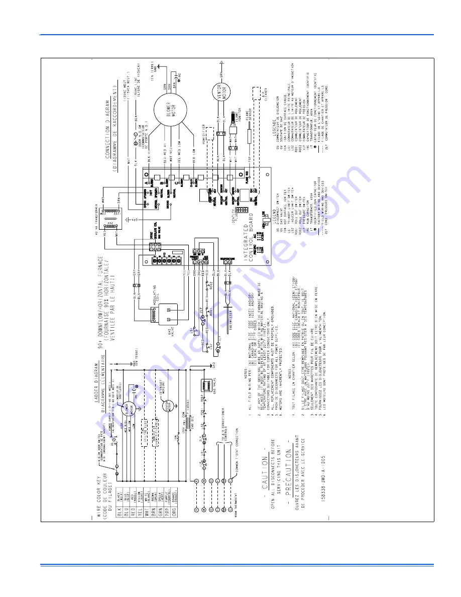
SECTION IV: WIRING DIAGRAM
FIGURE 9:
Wiring Diagram
Страница 1: ...have been wet or the furnace if deemed necessary FIRE OR EXPLOSION HAZARD Failure to follow safety warnings exactly could result in serious injury death or property damage Do not store or use gasoline or other flammable vapors and liquids in the vicinity of this or any other appliance WHAT TO DO IF YOU SMELL GAS Do not try to light any appliance Do not touch any electrical switch do not use any ph...
Страница 2: ...e furnace casing making sure the physical support is sound without sagging cracks or gaps Examine the furnace base making sure it is physically sound without cracks gaps or sagging and has a good seal 5 Examine the furnace casing for obvious signs of deterioration 6 Examine the burner flames to make sure they are in good adjust ment Refer to the pictorial sketch shown in Figure 2 as a compari son ...
Страница 3: ...safety information above 2 Set the thermostat to the lowest setting 3 Turn off all electric power to the appliance 4 Remove burner door 5 Move gas control switch to the OFF position Do not force 6 Wait five 5 minutes to clear out any gas If you then smell gas STOP Follow B in the safety information above If you don t smell gas go to next step 7 Move gas control switch to the ON position Do not for...
Страница 4: ...ir filter in a rack attached to the cas ing of the furnace or placed in the return air duct You can gain access to the filter by pulling on the door or unscrewing the retaining screw then slide the filter s out of its channel Replace throw away filter s with the same size new filter s Throw away filter s may be replaced with cleanable filter s at this time Cleanable filter s may be cleaned as desc...
Страница 5: ... checked periodically for dirt accumulation If cleaning is required follow this procedure 1 Turn off the electrical power to the unit 2 Turn off the gas supply at the external manual shut off valve and loosen the ground union joint 3 Remove the burner door and remove the burner box cover 4 Disconnect wires from flame sensor rollout switch and HSI igniter Remove igniter carefully as it is easily br...
Страница 6: ...tis fied the furnace control recalculates the demand and a new firing rate a If demand exceeds the minimum firing rate the burners will continue to fire at a recalculated reduced firing rate decreas ing if the thermostat remains off for a defined time b If demand does not exceed the minimum firing rate the burn ers will shut off immediately 8 After the burners shut off the circulating blower will ...
Страница 7: ... system faulty blower motor restricted circulating airflow or an open fuse on the con trol board Five Red Flashes Rollout switch auxiliary limit switch or condensate pressure switch open Check the rollout switch on the side of the burner box It is a manual reset switch To reset push the small button in the center of the switch If it cannot be reset or if the switch trips again con tact a qualified...
Страница 8: ... Group SECTION III REPLACEMENT PARTS LIST 2 7 13 14 11 5 9 37 10 80 46 45 47 54 64 19 18 27 28 33 30 35 72 71 69 68 1 2 4 5 6 14 15 16 62 55 56 54 21 23 22 31 26 25 59 48 57 60 53 44 43 51 52 49 50 18 6 9 37 14 24 20 29 31 39 43 63 46 10 ...
Страница 9: ...3 PLUG WINDOW CLEAR 1 5 44 COMBUSTION AIR TRANSITION 3 WAY 45 TUBING SILICONE Gray 188 ID 2 83 ft Req d 46 TUBING SILICONE Preformed 47 TUBING SILICONE Gray 188 ID 1 25 ft Req d 48 GASKET COMBUSTION BLOWER 49 GASKET CONDENSATE PAN 50 GASKET UPPER CONDENSATE PAN 2 Req d 51 GASKET GAS CONTROLS 52 GASKET CONDENSING COIL 53 GASKET COMBUSTION AIR TRANSITION 54 VENT PIPE 2 X 15 25 LG 55 GROMMET MOTOR 3 ...
Страница 10: ...NET 1CB0321 21 CABINET 1CB0324 24 1 2 CABINET 1TK0917 COIL TRANSITION KIT 17 1 2 CABINET 1TK0921 21 CABINET 1TK0924 24 1 2 CABINET REPLACEMENT PART CONTACT INFORMATION This is a generic parts list To request a complete parts list refer to the contact information below Visit our website at www source1parts com for the following information 1 Search for a part or browse the catalog 2 Find a dealer o...
Страница 11: ...292451 UUM A 0108 Unitary Products Group 11 SECTION IV WIRING DIAGRAM FIGURE 9 Wiring Diagram ...
Страница 12: ...o products installed in the United States and Canada EXCLUSIONS This warranty does not cover any 1 Shipping labor or material charges 2 Damages resulting from transportation installation or servicing 3 Damages resulting from accident abuse fire flood alteration or acts of God tampering altering defacing or removing the product serial number will serve to void this warranty 4 Damages resulting from...