Tianjin Yolin Technology Co. Ltd.
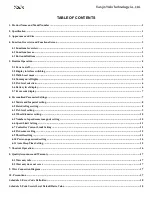
Electric Bike Display
User’s Manual
YL81F
Страница 1: ...Tianjin Yolin Technology Co Ltd Electric Bike Display User s Manual YL81F...
Страница 2: ...nalized Parameter Settings 7 6 1 Metric and Imperial setting 8 6 2 Rated voltage setting 8 6 3 PAS level setting 9 6 4 Wheel diameter setting 10 6 5 Number of speed sensor magnets setting 10 6 6 Speed...
Страница 3: ...cification 24V 36V 48V power supply Display rated current 15mA Display maximum current 30mA Shutdown leakage current 1uA Supplied current to the controller 50mA Operating temperature 20 60 Storage tem...
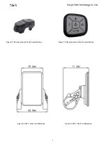
Страница 4: ...2 Figure 3 2 Physical picture of the K5 control button Figure 3 3 Physical picture of the K6 control button Figure 3 4 90T V Front View Dimension Figure 3 5 90T V Side View Dimension...
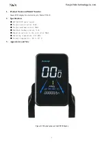
Страница 5: ...optional Bluetooth connection indicator optional Personalized parameter settings e g wheel diameter speed limit rated voltage PAS parameter password and controller current limit setting etc Factory de...
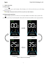
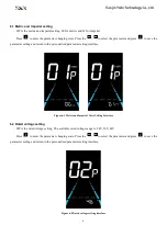
Страница 6: ...the leakage current is less than 1uA The display will automatically shut off if it is not used for more than 10 minutes 5 2 Display interface switching When the display is powered on it will show the...
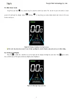
Страница 7: ...the state before walk boost Figure 5 2 Helping to implement the display screen The walk boost mode can only be used when pushing the electric bicycle please do not use it while riding 5 4 Turning on o...
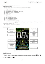
Страница 8: ...display The Battery level is shown as 5 bars When the battery is full charged all of the 5 bars lighten up When the battery is fully depleted the bar will begin to flash warning the user to charge the...
Страница 9: ...personalized parameter setting interface 2 Press to toggle between the personalized parameter setting interface and press to enter the parameter changing state 3 Press to select the parameter long pre...
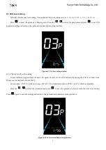
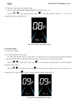
Страница 10: ...rn to the personalized parameter setting interface Figure 6 1 Metric and Imperial Units Setting Interface 6 2 Rated voltage setting 02P is the rated voltage setting The available rated voltage range i...
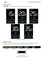
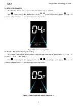
Страница 11: ...6 3 1 PAS level ratio value setting To meet different requirements for users the speed of every level can be adjusted by setting the PAS level ratio value Please see the details from Schedule 2 For e...
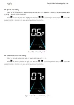
Страница 12: ...ng interface Figure 6 5 Wheel diameter setting interface 6 5 Number of speed sensor magnets setting 05P is the speed sensor magnet number setting The adjustable speed sensor magnet number range is 1 1...
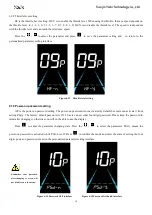
Страница 13: ...save the parameter setting and return to the personalized parameter setting interface Figure 6 7 Speed limit setting interface 6 7 Controller Current Limit Setting 07P is the controller current limit...
Страница 14: ...the parameter setting and enter into 6 8 2 PAS sensor sensitivity setting interface Figure 6 9 PAS sensor direction setting interface 6 8 2 PAS sensor sensitivity setting SCN is the PAS sensor sensit...
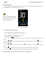
Страница 15: ...setting HL is the throttle 6KM H walk boost setting HL Y is to enable the walk boost and the speed will maintain at 6KM H when using throttle HL Y is to disable the walk boost and it can reach the max...
Страница 16: ...on password setting The power on password is not activated by default but users can activate it from setting PSd y The factory default password is 1212 Users can set other four digit password Please k...
Страница 17: ...ord setting interface 6 11 Auto Sleep Time Setting 11P is the auto sleep time setting To save the battery power and reach higher range this display will be turned off after it has not been used for a...
Страница 18: ...a few seconds and then automatically start to restore the factory default settings The display will automatically exit to setting interface after the restoration Figure 7 1 Restore Factory Default Se...
Страница 19: ...1 Wire Connection Diagram Table 9 1 Standard connector wire sequence table Standard Wire Sequence Standard wire color Function 1 Red VCC Display power wire 2 Blue Kp Controller power wire 3 Black GND...
Страница 20: ...ure E022 Throttle failure E025 Brake failure E023 Motor phase failure E030 Communication failure breakdown Schedule 2 Pedal Assist Level Default Ratio Value Level Level selection 1 2 3 4 5 6 7 8 9 0 3...