background image

1-7

IM WT5000-02EN

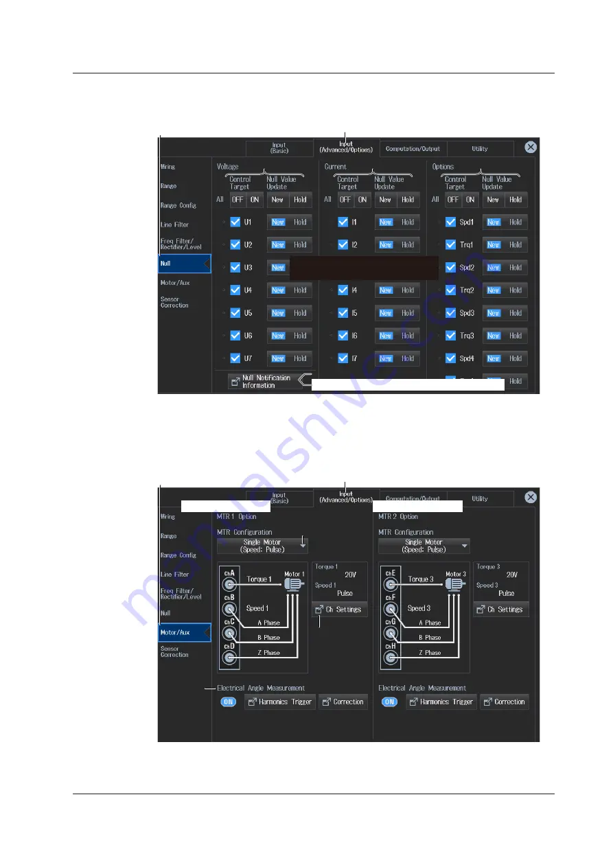
Null Feature Settings (Null)  

► section 11.1

3.

 Tap 

Null

. A null feature setup screen appears.


Input (Advanced/Options) tab

Null button

Null 

For voltage

For current

Enables or disables the Null feature

Updates or holds the Null value

Power-on time/warm-up completion time

For motor/Aux

(option)

Motor Evaluation and Auxiliary Input Settings (Motor/Aux)   


► section 9.1

3.

 Tap 

Motor/Au

x. A Motor/Aux screen (MTR1/MTR2) appears. 

The following screen is an example for a model with both the /MTR1 and /MTR2 options.


Input (Advanced/Options) tab

Motor/Aux button

MTR configuration 

(select the device to be 

evaluated (Motor/Aux))

Set Motor/Aux.

Electrical 

angle 

measurement

/MTR1 options screen

/MTR2 options screen

1.2  Input Settings Overview

Содержание WT5000

Страница 1: ...IM WT5000 02EN 4th Edition Precision Power Analyzer WT5000 ...

Страница 2: ...wide is provided on the following sheet Document No Description PIM 113 01Z2 List of worldwide contacts Notes The contents of this manual are subject to change without prior notice as a result of continuing improvements to the instrument s performance and functions The figures given in this manual may differ from those that actually appear on your screen Every effort has been made in the preparati...

Страница 3: ...er or damage to the instrument or user s data and precautions that can be taken to prevent such occurrences French AVERTISSEMENT Attire l attention sur des gestes ou des conditions susceptibles de provoquer des blessures graves voire mortelles et sur les précautions de sécurité pouvant prévenir de tels accidents ATTENTION Attire l attention sur des gestes ou des conditions susceptibles de provoque...

Страница 4: ...e screen Range icon Use this icon to set the voltage range and current range including the external current sensor Update Rate Averaging icon Use this icon to set the data update interval and averaging Filter icon Use this icon to set the line filter and frequency filter Store Data Save icon Use this icon to store data and save data Integration icon Use this icon to control the integration feature...

Страница 5: ...es the displayed page Page Up Page Down Switches the numeric data screen shown in each display format This is the same as tapping and on the measurement display screen see section 3 2 Set the graph display format Wave Trend Bar Vector see sections 6 2 to 6 5 Switch the displayed group Group1 to Group4 see sections 6 2 to 6 5 Set the display format see sections 6 2 to 6 5 Set the divisions and time...

Страница 6: ...can use these when Display All Elements is set to OFF Note On the All Items display you cannot select individual displayed items and change their measurement function element or wiring unit If you switch to the Matrix display you can change the measurement functions elements and wiring units using the displayed table see the previous page On the 4 8 and 16 Value Displays Select the displayed item ...

Страница 7: ... See section 3 1 Set the displayed item Set the displayed measurement function see section 3 1 On the Hrm List Single or Hrm List Dual Display Select the displayed harmonic data column This is for Hrm List Dual Select 1 left column or 2 right column You can also tap the measurement display screen see page vii Closes the menu Selects the input element Element1 to Element7 or wiring unit ΣA ΣB ΣC to...

Страница 8: ...me operation as selecting the displayed item number on the 4 8 and 16 value displays and matrix display and selecting the displayed harmonic data column on the Hrm List Single or Hrm List Dual display 1 Tap the Item No 2 area The Item No display changes to 2 2 Set the items e g function Item No display Items Measurement display screen Small menu Resetting the Displayed Items Closes the menu Set th...

Страница 9: ... range settings see section 2 5 When the input element is a 760903 current sensor element Configuring the External Current Sensor Closes the menu Turns the external current sensor on and off Set the sensor conversion ratio see section 2 3 Set the sensor conversion ratio preset see section 2 3 The sensor conversion ratio preset is currently not available When the input element is 760901 or 760902 W...

Страница 10: ... response for the parameters see section 2 10 You can use this when the computing method is set to digital filter average Update Rate menu Averaging menu Advanced data update interval and averaging settings For details on the data update interval see section 2 10 For details on averaging see section 2 13 Turns averaging on and off Set the averaging type for the parameters see section 2 13 Set the ...

Страница 11: ...quency filter Set the line filter Turns the filter on and off Set the cutoff frequency see section 2 7 Advanced filter settings see section 2 7 This instrument has three measurement modes see section 1 1 A filter menu is displayed according to the measurement mode Shown above is the menu for normal measurement mode Menu Icons ...

Страница 12: ...rarily paused Tap REC to resume storage Ends storage Storage stops and the storage state is reset Writing the stored data to the file is completed and the file is closed Configure storage see sections 7 1 to 7 3 Select the data you want to save Data whose check box is selected will be saved Configure data saving see sections 8 2 to 8 4 Starts saving Store menu Data Save menu Storage destination dr...

Страница 13: ...e and integrated value All integration data is deleted and the no data display appears The STOP key in the INTEGRATION area turns off Turns independent computation on and off Select the input elements that you want independent computation to be performed on You can set this when independent computation is set to on Collectively selects input elements to perform independent computation on All ON Al...

Страница 14: ...the measurement conditions and judgment conditions see section 14 1 Normal voltage fluctuation flicker measurement Measurement of dmax caused by manual switching Closes the menu Set the measurement mode to dmax Switch the element you want to display the measurement data of Executes initialization Starts a measurement Reset Completes the measurement and displays the judgment Changes the observation...

Страница 15: ...utes the holding of measured values OFF ON When holding is in progress the HOLD key illuminates Executes single measurement You can execute this once while holding is in progress Enables or disables the null feature OFF ON While the null feature is enabled the NULL key illuminates Configure the null feature see section 11 1 Executes zero level compensation Cal see section 11 2 Set the sensor corre...

Страница 16: ...t Period 2 27 2 9 Setting the Crest Factor 2 29 2 10 Setting the Data Update Interval 2 30 2 11 Setting the Efficiency Equation 2 32 2 12 Setting the Delta Computation 2 33 2 13 Setting Averaging 2 34 2 14 Master slave Synchronous Measurement 2 35 Chapter 3 Power Display Numeric Display 3 1 Setting the Display Format 3 1 3 2 Displaying the Voltage Current Active Power and Power Factor 3 9 3 3 Disp...

Страница 17: ...uation numeric display 9 12 Chapter 10 Holding Measured Values and Performing Single Measurements 10 1 Holding Measured Values 10 1 10 2 Single Measurement 10 3 Chapter 11 Null Feature DC offset cancelation and Zero Level Compensation Cal 11 1 Configuring Enabling and Disabling the Null Feature 11 1 11 2 Zero Level Compensation Cal 11 3 Chapter 12 Cursor Measurement 12 1 Cursor Measurement on Wave...

Страница 18: ...SB Keyboard Languages 16 6 16 5 Setting the Screen Brightness and Turning the Screen Off 16 7 16 6 Environment Settings Preference 16 8 16 7 Self Test 16 9 16 8 Displaying the Message Log 16 11 16 9 Viewing the Instrument Information and Current Sensor Status 16 12 16 10 Locking the Touch Panel and Front Panel Operations 16 14 Appendix Appendix 1 Messages and Corrective Actions App 1 Index Content...

Страница 19: ...monic measurements See chapter 13 IEC Voltage fluctuation flicker measurement Flicker This mode has a setup menu for IEC voltage fluctuation flicker measurements See chapter 14 Measurement Mode Measurement Mode 1 Tap the Setup icon or press MENU under SETUP The setup menu screen appears Selects the measurement mode Normal Displays the navigation window Various overview screens Input settings overv...

Страница 20: ...verview screen Input Settings Basic Overview Input Basic 1 Tap the Setup icon or press MENU under SETUP 2 Tap the Input Basic tab An input settings basic measurement conditions overview screen appears Pressing ESC closes the overview screen Input Basic tab Shows the settings of Element1 to Element7 You can also set the input element items When the input element is 760901 or 760902 When the input e...

Страница 21: ...es guide Set the current range see section 2 2 Current Range Current in the features guide Configure the external current sensor see section 2 3 External Current Sensor On Off Ext Sensor in the features guide Set the voltage transformer VT and current transformer CT ratios see section 2 4 Scaling Scaling in the features guide Configure the line filter and frequency filter settings see section 2 7 ...

Страница 22: ...tab Wiring button When the input element is 760901 or 760902 When the input element is 760903 Wiring diagram Wiring unit Wiring system External current sensor Current measurement terminal The display showing the wiring diagram and wiring units changes depending on the specified wiring system Common Measurement Range Settings Range section 2 1 2 3 2 9 3 Tap Range A setup screen appears for common m...

Страница 23: ... background of the specified measurement range to switch to when a peek over range occurs Peak Over Jump is displayed in blue Switches between voltage and current Line Filter Settings Line Filter section 2 7 3 Tap Line Filter A line filter setup screen appears The following screen is an example when Advanced Settings are on You can set the HFR AAF DLF N and DLF H filters separately Input Advanced ...

Страница 24: ...d Settings are on You can set the HPF Rectifier LPF and Level separately Input Advanced Options tab Freq Filter Rectifier Level button Sync Source Freq Measurement button Turns the advanced frequency filter settings on and off Frequency filter HPF Frequency filter LPF Voltage current signal rectifier Voltage current cross level Second Frequency Measurement Filter Settings Freq2 Measurement Freq Fi...

Страница 25: ...m up completion time For motor Aux option Motor Evaluation and Auxiliary Input Settings Motor Aux section 9 1 3 Tap Motor Aux A Motor Aux screen MTR1 MTR2 appears The following screen is an example for a model with both the MTR1 and MTR2 options Input Advanced Options tab Motor Aux button MTR configuration select the device to be evaluated Motor Aux Set Motor Aux Electrical angle measurement MTR1 ...

Страница 26: ...ion Settings Sensor Correction section 2 6 3 Tap Sensor Correction A sensor correction screen appears Input Advanced Options tab Sensor Correction button Current amplitude correction Current phase correction 1 2 Input Settings Overview ...

Страница 27: ...rview screen Computation and Output Settings Overview Computation Output 1 Tap the Setup icon or press MENU under SETUP 2 Tap Computation Output tab A computation and output settings overview screen appears Pressing ESC closes the overview screen Setting the Efficiency Equation Efficiency section 2 11 3 Tap Efficiency An efficiency equation setup screen appears Computation Output tab Efficiency bu...

Страница 28: ...y the setup menu screen from the navigation window that appears immediately after power on Displays the setup menu screen Navigation window Setting the Delta Computation ΔMeasure section 2 12 3 Tap ΔMeasure A delta computation setup screen appears Computation Output tab ΔMeasure button Delta computation type Delta computation mode Wiring information 1 3 Computation and Output Settings Overview ...

Страница 29: ...e Averaging button Data update interval Averaging Setting the Harmonic Measurement Harmonics section 5 1 3 Tap Harmonics A harmonic measurement setup screen appears Computation Output tab Harmonics button PLL source Input element Minimum harmonic order to be measured Maximum harmonic order to be measured Distortion factor equation Number of FFT points Harmonic measurement group 1 3 Computation and...

Страница 30: ...r defined events see section 3 5 Corrected power computation see section 3 3 Phase difference display format see section 3 4 Phase polarity see section 3 4 Master slave see section 2 14 Configuring the Numeric Custom and Graphic Displays Display sections 3 1 3 8 6 1 3 Tap Display A setup screen appears for the screen display format Computation Output tab Display button Screen display single split ...

Страница 31: ... see section 7 2 Storage destination see section 7 3 Configuring the Data Save Feature Data Save section 8 2 8 3 8 4 8 5 3 Tap Data Save A data save setup screen appears Computation Output tab Data Save button Data to save Numeric data items to save see section 8 3 Format color of screen images to save see section 8 4 Save destination see section 8 2 1 3 Computation and Output Settings Overview ...

Страница 32: ...Output tab Integration button Integration mode Integration timer Integration method Configuring the D A Output D A Output section 16 2 3 Tap D A Output A D A output setup screen appears Computation Output tab D A Output button D A output channels Output items of each channel Rated time of integrated D A output 1 3 Computation and Output Settings Overview ...

Страница 33: ...ettings overview screen appears Pressing ESC closes the overview screen System Configuration System Configuration section 16 3 16 4 16 5 16 6 3 Tap System Configuration A system settings overview appears Utility tab System Configuration button Date and time See section 3 6 in the Getting Started Guide IM WT5000 03EN Language see section 16 4 LCD off brightness see section 16 5 IEEE 1588 time synch...

Страница 34: ...n window that appears immediately after power on Displays the setup menu screen Navigation window Remote Control Settings Remote Control section 16 1 3 Tap Remote Control A remote control setup screen Network VXI 11 GP IB USB USB TMC appears Utility tab Remote Control button Network timeout GP IB address USB USB TMC Serial number Communication commands WT compatible commands IP address display 1 4...

Страница 35: ...p screen appears TCP IP Settings see section 15 2 Utility tab Network button Shows the TCP IP setup screen DHCP DNS FTP Server Settings see section 15 3 Web Server Settings see section 15 4 Utility tab Network button Shows the FTP Web server setup screen User name Password FTP server timeout 1 4 Utility Settings Overview ...

Страница 36: ... User name Password Host name of the FTP server on the network Network drive timeout SNTP date and time settings see section 15 6 Utility tab Network button Shows the SNTP setup screen SNTP server timeout SNTP server s host name Adjust the instrument s clock relative to the Greenwich Mean Time 1 4 Utility Settings Overview ...

Страница 37: ...7 3 Tap Selftest A self test setup screen appears Utility tab Selftest button Test item Message Log Display Message Log section 16 8 3 Tap Message Log A message log screen appears Utility tab Message Log button Message log 1 4 Utility Settings Overview ...

Страница 38: ... table of instrument information Tap Upgrade to display the Upgrade screen Utility tab System Overview button see section 16 9 Upgrade button Current Sensor Status Display Sensor Status section 16 9 3 Tap Sensor Status The current sensor statuses are listed Utility tab Sensor Status button 1 4 Utility Settings Overview ...

Страница 39: ...p the Setup icon or press MENU under SETUP The setup menu screen appears Loads setup data Shows information about the setup data currently loaded in this instrument Saves setup data File operation see section 8 6 Initializes setup data Displays the navigation window Various overview screens Input settings overview see section 1 2 Computation and output settings overview see section 1 3 Utility set...

Страница 40: ...ent see section 8 2 Save destination device Closes the menu Setting the Save Destination 3 Tap File List A file list appears Pressing ESC closes the file list 4 Select the save destination from the file list 5 Tap Save The setup data is saved in the save destination folder File operation see section 8 6 File path Currently selected folder path Starts saving File list 1 5 Saving Loading and Initial...

Страница 41: ...p data is set 4 Tap Load The setup data is loaded into the instrument File operation see section 8 6 File path Currently selected folder path Starts loading File list Initializing the Setup Data 2 Tap Initialize Settings A confirmation screen appears for executing the initialization 3 Tap OK The setup data of this instrument will be initialized 1 5 Saving Loading and Initializing Setup Data ...

Страница 42: ... the following procedure At Instrument Startup 1 On the navigation window that appears when the instrument starts tap Current Sensor Settings The current sensor setup menu screen appears Current Sensor Settings button From the Setup Menu after Instrument Startup 1 Tap the Setup icon or press MENU under SETUP The setup menu screen appears 2 Tap Navigation at the bottom of the setup menu screen A na...

Страница 43: ...voltage rate external current sensor conversion ratio see section 2 2 2 3 Current amplitude correction current phase correction see section 2 6 For details on the individual settings see the respective references 2 Tap Next or Back that appears at the bottom of the Terminal CT Sensor and subsequent setup screens The screen will switch to the next setup screen or previous setup screen You can also ...

Страница 44: ...up icon or press MENU under SETUP 2 Tap the Input Basic tab An input settings basic measurement conditions overview screen appears Pressing ESC closes the overview screen Input Basic tab When the input element is 760901 or 760902 When the input element is 760903 Set the wiring system Note You can also display the input settings basic measurement conditions overview screen by moving the cursor on t...

Страница 45: ...llest number Note You cannot set the wiring units for larger element numbers before the wiring units for smaller element numbers You cannot assign different types of input element to a wiring unit For the 760903 current sensor input element when Range Σ Link is set to ON the wiring unit cannot be set among elements whose CT Type or Input Resistance setting is different Range Σ Link Settings Range ...

Страница 46: ... see page iii Procedure Using the Keys other than SETUP see section 1 2 in IM WT5000 03EN Procedure Using the Setup Menu 1 Tap the Setup icon or press MENU under SETUP 2 Tap the Input Basic tab An input settings basic measurement conditions overview screen appears Pressing ESC closes the overview screen Input Basic tab When the input element is 760901 or 760902 When the input element is 760903 Set...

Страница 47: ...V Voltage range example of element 1 Operations in the Input Information Area See page 2 8 Available voltage range options When the Crest Factor Is Set to CF3 When the Crest Factor Is Set to CF6 or CF6A 1 5 V 3 V 6 V 10 V 15 V 30 V 60 V 100 V 150 V 300 V 600 V 1000 V 0 75 V 1 5 V 3 V 5 V 7 5 V 15 V 30 V 50 V 75 V 150 V 300 V 500 V Note When range Σ link see section 2 1 is set to on the voltage ran...

Страница 48: ...on 2 3 Configure the current sensor see section 2 3 Operations in the Input Information Area See page 2 8 Available current range options 30 A Input Element 760901 When the Crest Factor Is Set to CF3 When the Crest Factor Is Set to CF6 or CF6A 500 mA 1 A 2 A 5 A 10 A 20 A 30 A 250 mA 500 mA 1 A 2 5 A 5 A 10 A 15 A 5 A Input Element 760902 When the Crest Factor Is Set to CF3 When the Crest Factor I...

Страница 49: ...cordingly Further Scaling is set to ON and CT Ratio is set to the default value according to CT Type Change these settings if necessary If CT Type is set to Custom proceed to step 8 If you do not want to change the input resistance proceed to step 10 8 Tap Input Resistance The Input Resistance menu appears 9 Select the input resistance 10 Follow the instructions below to set the current range Enab...

Страница 50: ...erminal to Probe Select the probe type When the probe type is Custom select the output voltage rate Available current range options For the current range options see Current Range Current CURRENT RANGE in the features guide Note When range Σ link see section 2 1 is set to on the current ranges and current measurement terminal settings of the input elements assigned to the same wiring unit are set ...

Страница 51: ...ted in section 2 5 Select options See Procedure Using Keys in section 9 1 This is not used in this section Procedure Using the Input Information Area Elements tab If you use the input information area shown on the right side of the screen you can set the voltage range and current range while viewing the measurements The input information area is displayed when you close the overview screen 1 Tap t...

Страница 52: ...wing setup methods Procedure Using the Setup Menu see chapter 1 Procedure Using the Menu Icons see page iii Procedure Using the Setup Menu 1 Tap the Setup icon or press MENU under SETUP 2 Tap the Input Basic tab An input settings basic measurement conditions overview screen appears Pressing ESC closes the overview screen Input Basic tab Set the current range Note You can also display the input set...

Страница 53: ...al current sensor to ON Set the sensor conversion ratio preset The sensor conversion ratio preset is currently not available Set the sensor conversion ratio 0 0001 to 99999 9999 Operations in the Input Information Area As explained in Current Range of section 2 2 the external current sensor range can also be set in the input information area see page 2 8 Available External Current Sensor Range Opt...

Страница 54: ...rent with a maximum value of 100 A using a current sensor that produces 10 mV when 1 A of current is flowing the maximum voltage that the current sensor produces is 10 mV A 100 A 1 V Therefore configure the settings as indicated below External current sensor range 1 V External current sensor conversion ratio 10 mV A Setting the Current Range Display Format Current Range Display Format 3 Tap the In...

Страница 55: ...explained earlier Note For details on the Range menu see page viii Procedure Using Keys You can also use the front panel keys to set the external current sensor range Select the element to be configured 1 to 7 Select the external current sensor range fixed You can select from the valid measurement ranges selected in section 2 5 Set the external current sensor range to auto Select options See Proce...

Страница 56: ...Procedure Using the Setup Menu 1 Tap the Setup icon or press MENU under SETUP 2 Tap the Input Basic tab An input settings basic measurement conditions overview screen appears Pressing ESC closes the overview screen Input Basic tab Set the VT ratio CT ratio and power coefficient Note You can also display the input settings basic measurement conditions overview screen by moving the cursor on the Inp...

Страница 57: ...cuit under measurement directly turn the VT CT scaling feature off If it is turned on the value will be further multiplied by the CT ratio Set the VT ratio 0 0001 to 99999 9999 Set the CT ratio 0 0001 to 99999 9999 Set the power coefficient scaling factor 0 0001 to 99999 9999 Set the CT ratio preset CT2000A CT1000A CT1000 CT200 CT60 Others Set this when using the dedicated CT Copies the coefficien...

Страница 58: ... set the valid measurement ranges from the available options Procedure Using the Setup Menu 1 Tap the Setup icon or press MENU under SETUP 2 Tap the Input Advanced Options tab An input settings advanced options overview screen appears Pressing ESC closes the overview screen 3 Tap Range Config A measurement range configuration setup screen appears Input Advanced Options tab Range Config button Set ...

Страница 59: ...ange is on you can turn it on by pressing AUTO the instrument operates as follows When a peak over range occurs the measurement range increases to the range specified here skipping the ranges in between When the measurement range to switch to when a peak over range occurs has not been selected the measurement range increases in the order of the specified valid measurement ranges Button for display...

Страница 60: ...Σ Link see section 2 1 is set to ON the input elements that are assigned to the same wiring unit are set to the same status If the measurement range to switch to when a peak over range occurs has been selected the range background is displayed in gray By tapping an input element or wiring unit you can set all ranges as valid measurement ranges All ON By tapping each range display you can collectiv...

Страница 61: ...50mV When Range Σ Link is set to on see section 2 1 the input elements that are assigned to the same wiring unit are set to the same range If auto range is on you can turn it on by pressing AUTO the instrument operates as follows When a peak over range occurs the measurement range increases to the range specified here skipping the ranges in between When the measurement range to switch to when a pe...

Страница 62: ...lect the item to set the current range of Terminal in Use Direct Sensor Ext Sensor Probe By tapping the asterisk of each range you can collectively set or not set the applicable ranges of all input elements or wiring units as valid measurement ranges All ON or All OFF Valid measurement range The measurement range switches in order between the selected ranges Ranges that are not selected are skippe...

Страница 63: ...ween I O item at the bottom Time difference between input and output Current phase correction Set the phase error between input and output 180 000 to 180 000 Set frequency 50 Hz 60 Hz 0 1 kHz to 999 9 kHz 1 MHz Turns the phase correction on and off Current amplitude correction Set the correction ratio 0 800000 to 1 200000 Turns current amplitude correction on and off Note You can also display the ...

Страница 64: ...figurable For details see the features guide Procedure Using the Setup Menu 1 Tap the Setup icon or press MENU under SETUP Setting the Line Filter and Frequency Filter Cutoff 2 Tap the Input Basic tab An input settings basic measurement conditions overview screen appears Pressing ESC closes the overview screen Input Basic tab Set the line filter Set the frequency filter Note You can also display t...

Страница 65: ...tings advanced options overview screen appears Pressing ESC closes the overview screen Setting the Line Filter Line Filter 3 Tap Line Filter A line filter setup screen appears When Line Filter Advanced Settings Is Set to OFF You can set the cutoff frequency and filter type Input Advanced Options tab Turns line filter advanced settings on or off Set the filter type Butterworth Bessel By tapping Cut...

Страница 66: ...set the value collectively for all elements By tapping HF Rejection input element 760903 only Anti Aliasing Filter Digital Line Filter Normal or Digital Line Filter Harmonics you can turn on or off the function on all elements collectively Set the cutoff frequency of the digital line filter for normal measurement 0 1 kHz to 100 0 kHz 0 1 kHz steps Turns the digital line filter for normal measureme...

Страница 67: ...r Advanced Settings Is Set to OFF You can set the cutoff frequency of the low pass filter LPF Input Advanced Options tab Turns freq filter advanced settings on or off Set sync source and frequency measurement By tapping Cutoff you can set the value collectively for all elements By tapping Freq Filter you can turn on or off the feature on all elements collectively Set the cutoff frequency of the lo...

Страница 68: ...on or off Sync Source Freq Configure the measurement By tapping Freq Filter you can turn on or off the feature on all elements collectively Set the cutoff frequency of the high pass filter HPF 0 1 Hz 1 Hz 10 Hz 0 1 kHz to 100 0 kHz 0 1 kHz steps Turns the high pass filter HPF on or off See section 2 8 Set the cutoff frequency of the low pass filter LPF 0 1 kHz to 100 0 kHz 0 1 kHz steps Turns the ...

Страница 69: ...ely Set the cutoff frequency of the high pass filter HPF 0 1 Hz 1 Hz 10 Hz 0 1 kHz to 100 0 kHz 0 1 kHz steps Turns the high pass filter HPF on or off Set the voltage cross level 0 0 to 100 0 0 1 steps You can use the voltage and current cross level settings when the high pass filter HPF is set to OFF Set the current cross level 0 0 to 100 0 0 1 steps Procedure Using the Menu Icons You can also us...

Страница 70: ...tails see the features guide Procedure Using the Setup Menu 1 Tap the Setup icon or press MENU under SETUP 2 Tap the Input Basic tab An input settings basic measurement conditions overview screen appears Pressing ESC closes the overview screen Input Basic tab Set the Sync Source If the computing method Measurement Method of the data update interval setup screen see section 2 10 is set to Digital F...

Страница 71: ...ce Freq Measurement sync source frequency measurement screen appears Input Advanced Options tab Turns freq filter advanced settings on or off Sync Source Freq Configure the measurement By tapping Voltage or Current you can turn on or off the feature on all elements collectively Turns the voltage rectifier on or off Turns the current rectifier on or off Set the voltage or current cross level When t...

Страница 72: ...er SETUP 2 Tap the Input Advanced Options tab An input settings advanced options overview screen appears Pressing ESC closes the overview screen Crest factor Crest Factor 3 Tap Range A setup screen appears for common measurement range items Input Advanced Options tab Range button Set the crest factor CF3 CF6 CF6A Note You can also display the input settings advanced options overview screen by movi...

Страница 73: ...ion Output tab A computation and output settings overview screen appears Pressing ESC closes the overview screen Setting the Data Update Interval Update Rate 3 Tap Update Rate Averaging A drop down list for setting the interval appears When the Data Update Mode Is Set to Constant Computation Output tab Set the data update interval Update Rate screen when the data update mode is set to Constant Set...

Страница 74: ... source is set to Ext Clk Set the trigger mode Auto Normal Set the trigger source U1 to U7 I1 to I7 Ext Clk Set the trigger level 0 0 to 100 0 You cannot use this when the trigger source is set to Ext Clk Procedure Using the Menu Icons You can also use the menu icons shown on the right side of the screen to set the data update interval 1 Tap the Update Rate Averaging menu icon An Update Rate Avera...

Страница 75: ...uation Wiring information Set the denominator and numerator of the efficiency equation to the active power and motor power measurement functions P1 to P71 PΣA to PΣC2 Pm1 to Pm43 Udef1 Udef2 You can set up to four equations η1 to η4 To add active powers and motor output and use them in efficiency equations use Udef1 and Udef2 Define Udef1 and Udef2 P1 to P71 PΣA to PΣC2 Pm1 to Pm43 1 Can be set wi...

Страница 76: ...mputation ΔMeasure 3 Tap ΔMeasure A delta computation setup screen appears Computation Output tab Set the delta computation equation Set the delta computation mode rms mean dc r mean ac Set the delta computation type ΣA ΣB ΣC The available options vary depending on the set wiring systems 1 1 Delta computation type 1P3W Wiring System 3P3W 3P4W 3P3W 3V3A Delta Computation Type Difference 3P3W 3V3A D...

Страница 77: ...ess MENU under SETUP 2 Tap Computation Output tab A computation and output settings overview screen appears Pressing ESC closes the overview screen Setting Averaging Averaging 3 Tap Update Rate Averaging A data update interval averaging setup screen appears Computation Output tab Update Rate Averaging button Averaging screen Turns averaging on and off Set the averaging type Exp Lin Set the attenua...

Страница 78: ...or press MENU under SETUP 2 Tap Computation Output tab A computation and output settings overview screen appears Pressing ESC closes the overview screen Setting the Master and Slave Sync Measure 3 Tap Measure An equation computation setup screen appears Computation Output tab Set the equation measurement Select master or slave Master Slave Note You can also display the computation output settings ...

Страница 79: ... or press MENU under SETUP 2 Tap Computation Output tab A computation and output settings overview screen appears Pressing ESC closes the overview screen Setting the Display Format Display 3 Tap Display A display format setup screen appears Computation Output tab Display button Set the numeric display format All Items 4 Items 8 Items 16 Items Matrix Hrm List Single Hrm List Dual User Set how many ...

Страница 80: ...numeric data in the top half of the screen and graphs see chapter 6 in the bottom half Graph graph display Numeric numeric display Shows graphs see chapter 6 in the top half of the screen and numeric data in the bottom half Graph graph display Graph graph display Shows graphs see chapter 6 in the top and bottom halves of the screen Custom custom display see section 3 8 Select one of the registered...

Страница 81: ...a single screen 4 Items 4 value display 8 Items 8 value display 16 Items 16 value display Matrix matrix display Measurement function Shows the measured values of each element All Items shows all values Switching the displayed page shows other items in this display area 3 1 Setting the Display Format ...

Страница 82: ...surement function that includes a harmonic order For details on how to switch pages see page 3 1 Closes the menu Turns the display of numeric data of all elements or all wiring units on and off If the total number of elements or wiring units is 8 or more set this to ON when you want to display the numeric data of all elements or all wiring units Turns the display frame on and off Scroll the screen...

Страница 83: ...input element or wiring unit to be configured Input element options When the displayed item is set to something other than motor evaluation Element1 to Element7 When the displayed item is set to motor evaluation Motor1 to Motor4 Wiring unit options ΣA ΣB ΣC Selects the harmonic order to be set This is for the harmonic orders display see section 5 2 Resets the displayed items On the Matrix Display ...

Страница 84: ...tion 5 2 Selects the input element or wiring unit to be configured Input element options When the displayed item is set to something other than motor evaluation Element1 to Element7 When the displayed item is set to motor evaluation Motor1 to Motor4 Wiring unit options ΣA ΣB ΣC Note On the harmonics list displays you can change the measurement function element and wiring unit for the selected list...

Страница 85: ...n on 1 page The screen is a display example of element 1 The screen is a display example of voltage Configuring the Columns to Display You can configure this on the Matrix display Select the displayed item number displayed column The number increases from left to right on the matrix display Example If you select 3 the third column from the left is displayed Closes the menu Resets displayed items S...

Страница 86: ...page iv Switching the Display Format NUMERIC key You can also use keys to perform Setting the Screen Display and Setting the Numeric Display Format described earlier NUMERIC Key top half Shows Numeric numeric display in the top half of the screen NUMERIC Key bottom half Shows Numeric numeric display in the bottom half of the screen NUMERIC Key single screen display Shows Numeric numeric display in...

Страница 87: ...i Measurement Display Screen Example of a 4 items display Measurement display of input element 1 Voltage true rms measurement Power active power measurement Current true rms measurement Power power factor measurement Switches the displayed page Page Up Page Down Switches to the measurement display of another input element Tap or to change the displayed page in order from the current number Tap the...

Страница 88: ...d fundamental component U peak maximum value U peak minimum value CfU crest factor Current measurement Current group Irms true rms value Imn rectified mean value calibrated to the rms value Idc simple average Irmn current rectified mean value Iac AC component Ifnd fundamental component I peak maximum value I peak minimum value CfU crest factor Measured power and power factor Power group P active p...

Страница 89: ... explains operating procedures using the following setup methods Procedure Using the Setup Menu see chapter 1 Procedure Using the Menu Icons see page iii Measurement Display Screen Example of a 4 items display Measurement display of input element 1 Computed apparent power value Computed corrected power value Computed reactive power value Switches the displayed page Page Up Page Down Switches to th...

Страница 90: ...ions Set the apparent power equation Urms Irms Umean Imean Udc Idc Umean Irms Urmean Irmean Set the apparent power and reactive power computation type Type 1 Type 2 Type 3 Set the corrected power standard to be applied Type1 Type2 Set the coefficients 0 0001 to 9 9999 When Select standard is Type1 set coefficients P1 and P2 Note You can also display the computation output settings overview screen ...

Страница 91: ...Sfnd fundamental apparent power Computed reactive power value Power group Q reactive power Qfnd fundamental reactive power Computed corrected power value Power group Pc Corrected Power Procedure Using the Menu Icons You can also use the menu icons shown on the right side of the screen to switch the displayed items 1 Tap the Display menu icon A Display menu appears in the sub menu area on the right...

Страница 92: ...sing the Setup Menu see chapter 1 Procedure Using the Menu Icons see page iii Measurement Display Screen Example of a 4 items display Measurement display of input element 1 Measured phase difference between voltage and current Measured frequency current Measured frequency voltage Switches the displayed page Page Up Page Down Switches to the measurement display of another input element Tap or to ch...

Страница 93: ...erence Display Mode Phase 3 Tap Measure An equation setup screen appears Computation Output tab Set equations Set the phase difference display format 180 360 Set the phase polarity Lead Lag Lead Lag Note You can also display the computation output settings overview screen by moving the cursor on the Computation Output tab using the arrow keys and then pressing SET 3 4 Displaying the Phase Differen...

Страница 94: ...l phase difference Measured frequency voltage Frequency group FreqU voltage frequency Freq2U current frequency Measured frequency current Frequency group FreqI current frequency Freq2I current frequency Procedure Using the Menu Icons You can also use the menu icons shown on the right side of the screen to switch the displayed items 1 Tap the Display menu icon A Display menu appears in the sub menu...

Страница 95: ...1 and voltage measurement range Ev2 Event example user defined event In addition this section explains operating procedures using the following setup methods Procedure Using the Setup Menu see chapter 1 Procedure Using the Menu Icons see page iii Measurement Display Screen Example of a 4 items display Measurement display of input element Numeric example Measured average active power Measured power...

Страница 96: ...een appears Computation Output tab Set equations Set computed values numeric Set computed values event 4 Tap User Defined Functions The following screen appears Displays the setup screen for user defined functions F1 to F5 F6 to F10 F11 to F15 F16 to F20 Set the computation OFF ON Set the computation name up to 8 characters Set equations 16 terms up to 60 characters Enter the unit using up to 8 ch...

Страница 97: ... as necessary You can also display the computation output settings overview screen by moving the cursor on the Computation Output tab using the arrow keys and then pressing SET Computed Value Event Display Mode User Defined Event 3 Tap Measure An equation setup screen appears 4 Tap User Defined Events The following screen appears Set the events OFF ON Set the event name up to 8 characters Set judg...

Страница 98: ...reen setting example Between 150 and 160 inclusive Selects the input element or wiring unit to be configured Input element options When the displayed item is set to something other than motor evaluation Element1 to Element7 When the displayed item is set to motor evaluation Motor1 to Motor4 Wiring unit options ΣA ΣB ΣC Setting Judgment Conditions example combination of events This is an explanatio...

Страница 99: ...value numeric User Func group F1 to F20 user defined function Computed value event User Event group Ev1 to Ev8 user defined event Procedure Using the Menu Icons You can also use the menu icons shown on the right side of the screen to switch the displayed items 1 Tap the Display menu icon A Display menu appears in the sub menu area on the right side of the screen By tapping the displayed items you ...

Страница 100: ...his section explains operating procedures using the following setup methods Procedure Using the Setup Menu see chapter 1 Procedure Using the Menu Icons see page iii Measurement Display Screen Example of a 4 items display Measurement display of input element 1 Maximum voltage true rms Maximum power active power Maximum current true rms Switches the displayed page Page Up Page Down Switches to the m...

Страница 101: ... to select ON Computation Output tab Set equations Set computed values numeric Maximum value display OFF ON 5 Tap User Defined Functions The following screen appears Displays the setup screen for user defined functions F1 to F5 F6 to F10 F11 to F15 F16 to F20 Set the computation OFF ON Set the computation name up to 8 characters Equation Examples MAXURMS E1 Maximum Urm of element 1 MAXIRMS E1 Maxi...

Страница 102: ...ew screen by moving the cursor on the Computation Output tab using the arrow keys and then pressing SET Switching the Displayed Items Items You can switch the measured value measurement function shown in the screen 3 Tap Display A display format setup screen Display Numeric Graph appears For details see section 3 1 4 Tap Items The following screen appears Closes the menu Set the displayed item You...

Страница 103: ...and output settings overview screen appears Pressing ESC closes the overview screen Setting the Display Format Display 3 Tap Display A display format setting screen appears Computation Output tab Display button Set the numeric display format to User Switches the displayed page Switches the numeric data screen shown in each display format Configure the display configuration Set the measured value m...

Страница 104: ...he display configuration is saved Total number of items Set the total number of numeric data boxes to display Displays the file list Set the save destination and file name Set where to save the display configuration For information about how to configure the file list display and how to operate files and folders see section 8 2 Selects the input element or wiring unit to be configured See On the 4...

Страница 105: ... not present in the save destination folder of the display configuration file Procedure Using the Menu Icons You can also use the menu icons shown on the right side of the screen to set the display format 1 Tap the Display menu icon A Display menu appears in the sub menu area on the right side of the screen By tapping the displayed items you can specify the same settings as when using the screen e...

Страница 106: ...ion the settings may be invalid or the settings may not be configurable For details see the features guide Procedure Using the Setup Menu 1 Tap the Setup icon or press MENU under SETUP 2 Tap the Computation Output tab A computation and output settings overview screen appears Pressing ESC closes the overview screen Setting the Display Format Display 3 Tap Display A display format setting screen app...

Страница 107: ... Delete The registered contents are deleted Set the registration name of the screen configuration For instructions on how to enter characters see section 3 3 in the Getting Started Guide IM WT5000 03EN New registration The current screen configuration is registered as a new configuration Tap an unregistered tab Procedure Using the Menu Icons You can also use the menu icons shown on the right side ...

Страница 108: ...key Displays the custom screen Each time you press CUSTOM the screen configuration changes in order between registration tabs 1 2 3 4 and 5 Unregistered tabs are skipped If there are no screen configurations registered in any of the registration tabs the screen does not switch to the custom screen 3 8 Custom Display ...

Страница 109: ...edure Using the Setup Menu see chapter 1 Procedure Using the Menu Icons see page iii Procedure Using the Keys other than SETUP see section 1 2 in IM WT5000 03EN Procedure Using the Setup Menu 1 Tap the Setup icon or press MENU under SETUP 2 Tap Computation Output tab A computation and output settings overview screen appears Pressing ESC closes the overview screen Setting Integration Conditions Int...

Страница 110: ...sing the arrow keys and then pressing SET Setting the Integration Timer Timer 4 Tap Integration Timer The following screen appears When independent computation is off Set the integration timer 00000 hours 00 minutes 00 seconds to 10000 hours 00 minutes 00 seconds When Mode is set to Normal and the integration timer is 00000 00 00 the instrument is in manual integration mode When independent comput...

Страница 111: ...hours 59 minutes 59 seconds Set the scheduled time to the current time Scheduled integration end time Set the scheduled time to the integration start time Tap Start Tap End When Independent Integration Is Enabled Set the scheduled start time and scheduled end time year month day 00 hours 00 minutes 00 seconds 23 hours 59 minutes 59 seconds Set the scheduled time to the current time Set the schedul...

Страница 112: ...Even if you select input elements that independent integration will be performed on independent integration may not be performed due to the wiring system setting or the independent input element configuration see the features guide Element number display Setting the Watt Hour Integration Method for Each Polarity WP Type 4 Tap WP Type The following screen appears Select the integration method setup...

Страница 113: ...the menu icons shown on the right side of the screen to set the integration conditions 1 Tap the Integration menu icon An Integration menu appears in the sub menu area on the right side of the screen By tapping the displayed items you can specify the same settings as when using the screen explained earlier Note For details on the Integration menu see page xii Procedure Using Keys You can also use ...

Страница 114: ...xplains operating procedures using the following setup methods Procedure Using the Setup Menu see chapter 1 Procedure Using the Menu Icons see page iii Procedure Using the Keys other than SETUP see section 1 2 in IM WT5000 03EN Measurement Display Screen Example of a 4 items display Measurement display of input element 1 Measured sum of positive and negative watt hours Measured volt ampere hours M...

Страница 115: ...playing integration Integrated value Integration group ITime integration time WP sum of positive and negative watt hours WP sum of positive P values WP sum of negative P values q sum of positive and negative ampere hours q sum of positive I values q sum of negative I values WS volt ampere hour WQ var hours Procedure Using the Menu Icons You can also use the menu icons shown on the right side of th...

Страница 116: ...integration Integration stops automatically according to the specified integration conditions The START key in the INTEGRATION area turns off and the STOP key turns on Resets the integration time and integrated value All integration data is deleted and the no data display appears The STOP key in the INTEGRATION area turns off Integration Status Display The integration status running paused end ind...

Страница 117: ... to 3 Example Integration paused on elements 1 to 3 When you execute reset the integration information is cleared and the STOP icons return to displaying numbers When integration ends after the specified timer value elapses or when the scheduled real time integration time is reached the elements selected for integration execution show STOP icons Unlike pausing you need to reset the integration aft...

Страница 118: ...nt there is a limitation on the measurement functions that can be measured See the appendix in the Getting Started Guide IM WT5000 03EN Procedure Using the Setup Menu 1 Tap the Setup icon or press MENU under SETUP 2 Tap Computation Output tab A computation and output settings overview screen appears Pressing ESC closes the overview screen Setting the Harmonic Measurement Harmonics 3 Tap Harmonics ...

Страница 119: ...ation Output tab using the arrow keys and then pressing SET Setting the Input Element Group Element Set 4 Tap Elements The Element Settings screen appears Configure the input element groups Hrm 1 Hrm 2 Input elements that are assigned to the same wiring unit are set to the same group 5 1 Setting Harmonic Measurement Conditions ...

Страница 120: ...monic current 50th harmonic Measured harmonic power factor 50th harmonic Switches the displayed page Page Up Page Down Switches to the measurement display of another input element Tap or to change the displayed page in order from the current number Tap the number directly to change to the number display page If you hold your finger down on the 4 8 16 value matrix or harmonics display for at least ...

Страница 121: ...oltage distortion factor Ihdf k harmonic current distortion factor Phdf k harmonic active power distortion factor Harmonics Harmonics Group Uthd total harmonic voltage distortion Ithd total harmonic current distortion Pthd total harmonic active power distortion Uthf voltage telephone harmonic factor Ithf current telephone harmonic factor Utif voltage telephone influence factor Itif current telepho...

Страница 122: ...layed group Group1 to Group4 Switches the graph group shown in each display format Switches the displayed items Select the measured values you want to graph The menu varies depending on the graph display type For details see the graph display explanations in sections 6 2 to 6 5 Cursor measurement Set the display format Set the screen divisions time scale etc The menu varies depending on the graph ...

Страница 123: ...m halves of the screen Numeric numeric display Graph graph display Shows numeric data see chapter 3 in the top half of the screen and graphs in the bottom half Graph graph display Numeric numeric display Show graphs in the top half of the screen and numeric data see chapter 3 in the bottom half Graph graph display Graph graph display Shows graphs in the top and bottom halves of the screen Example ...

Страница 124: ...d earlier Note For details on the Display menu see page iv Switching the Display Format GRAPH key You can also use keys to perform Setting the Screen Display described earlier and Setting the Graph Display Type GRAPH key bottom half of the screen Shows graphs in the bottom half of the screen GRAPH key single screen display Shows graphs in a single screen GRAPH key top half of the screen Shows grap...

Страница 125: ...guide Using an example this section explains how to display measurement results with waveforms In addition this section explains operating procedures using the following setup methods Procedure Using the Setup Menu see chapter 1 Procedure Using the Menu Icons see page iii Waveform Display Screen Example of group1 dual display Waveform display of input element 1 Voltage waveform Current waveform Pr...

Страница 126: ...he voltages and currents of the input elements to be displayed with waveforms 6 Tap Items A Wave Items screen appears 7 Tap the Display Mapping tab Turn the display on or off and map waveforms Display Mapping tab Set waveform mapping Auto Fixed User Displayed item preset buttons Turns the preset item display on and off The display can be turned on or off for each item Waveform can be mapped for ea...

Страница 127: ...ew seconds in the group display area in the upper right of the Graph screen Set the time scale 0 01 ms to specified data update interval1 Advanced Waveform Display Advanced 7 Tap Advanced A Form screen appears Closes the menu Set the scale value display OFF ON Set the display interpolation Set the grid Set the waveform label display OFF ON Items that are marked with are shared among all groups Pro...

Страница 128: ...graphs In addition this section explains operating procedures using the following setup methods Procedure Using the Setup Menu see chapter 1 Procedure Using the Menu Icons see page iii Trend Display Screen Example of group1 dual display Trend display of input element 1 Voltage trend Current trend Procedure Using the Setup Menu 1 Tap the Setup icon or press MENU under SETUP 2 Tap Computation Output...

Страница 129: ...s off Set the graphs of trend 1 to trend 8 Set the graphs of trend 1 to trend 8 Set the upper and lower limits 9 999 T to 9 999 T These settings can be set when vertical scale mode is set to Manual Select the vertical scale s setup method Auto Manual Set the harmonic order Total 0 to 500 You can set this setting when the measurement function includes a harmonic order Set the measurement function f...

Страница 130: ...trend Items that are marked with are shared among all groups Like the graph display pinch in or pinch out to switch the time scale see section 6 2 Advanced Waveform Display Advanced 7 Tap Advanced A Form screen appears Closes the menu Set the scale value display OFF ON Set the display interpolation Set the grid Set the waveform label display OFF ON Items that are marked with are shared among all g...

Страница 131: ...witch the displayed items 1 Tap the Display menu icon A Display menu appears in the sub menu area on the right side of the screen By tapping the displayed items you can specify the same operation as explained in Switching the Displayed Items described earlier Note For details on the Display menu see page iv 6 3 Trend Display ...

Страница 132: ...erating procedures using the following setup methods Procedure Using the Setup Menu see chapter 1 Procedure Using the Menu Icons see page iii Bar Graph Display Screen example of Group1 Triad display Bar graph display of input element 1 Bar graph of voltage U1 Item No 1 display Bar graph of current I1 Item No 2 display Bar graph of power P1 Item No 3 display Procedure Using the Setup Menu 1 Tap the...

Страница 133: ...displayed item You can set the following items for displaying measurement functions U harmonic voltage I harmonic current P harmonic active power S harmonic apparent power Q harmonic reactive power λ harmonic power factor Φ phase difference between harmonic voltage and harmonic current ΦU phase difference between each harmonic voltage and the fundamental wave ΦI phase difference between each harmo...

Страница 134: ...armonic order 10 to 500 You can set the range to any value provided that the end harmonic order is larger than the start harmonic order by 10 or more Procedure Using the Menu Icons You can also use the menu icons shown on the right side of the screen to switch the displayed items 1 Tap the Display menu icon A Display menu appears in the sub menu area on the right side of the screen By tapping the ...

Страница 135: ...dures using the following setup methods Procedure Using the Setup Menu see chapter 1 Procedure Using the Menu Icons see page iii Vector Display Screen example of Group1 ΣA display Vector display of wiring unit A Numeric display magnitude of input element 1 Numeric display magnitude of input element 2 Numeric display magnitude of input element 3 Numeric display phase difference of wiring unit A Per...

Страница 136: ...isplay flick to switch the display group see section 6 2 Switching the Displayed Items Items Select the input element or wiring unit to display the vectors of 6 Tap Items A Vector Items screen appears Closes the menu Set the element and wiring unit Element 1 Element 7 ΣA ΣC Set the zoom factor 0 100 to 100 000 Set the zoom factor of fundamental wave U 1 or I 1 The value that indicates the size of ...

Страница 137: ...Graph of Group2 to Vector Example of Item No set to 1 and Object set to ΣB see Switching the Displayed Items Items on the previous page Set Graph of Group1 to Vector Example of Item No set to 1 and Object set to ΣA see Switching the Displayed Items Items on the previous page Setting the Display Format Form Set whether to show numeric data on the Graph screen 6 Tap Form A Vector Form screen appears...

Страница 138: ...witch the displayed items 1 Tap the Display menu icon A Display menu appears in the sub menu area on the right side of the screen By tapping the displayed items you can specify the same operation as explained in Switching the Displayed Items described earlier Note For details on the Display menu see page iv 6 5 Vector Display ...

Страница 139: ...tings overview screen appears Pressing ESC closes the overview screen Configuring the Storage Store 3 Tap Store A Store screen appears Computation Output tab Configure the storage Set the storage mode Manual Real Time Integ Sync Event Single Shot Set the storage count Infinite 1 to 9999999 Sets the storage count to its maximum You can set the storage count to its maximum which is calculated automa...

Страница 140: ...nternal memory Note The maximum number of times that storage can be performed depends on the number of stored items that you have set and the free space at the save destination For details on how to set the stored items see section 7 2 For details on how to set the save destination see section 7 3 Setting the Storage Control When the Storage Mode Is Manual Computation Output tab Configure the stor...

Страница 141: ...art of storage You cannot set this when the storage interval is set to 00 00 00 OFF Not be saved ON Saved Setting the Scheduled Start Time Tap Start Time or End Time A Real time Control screen appears Scheduled storage start time Set the scheduled start and stop times Year month day 00 hours 00 minutes 00 seconds to 23 hours 59 minutes 59 seconds Set the scheduled time to the current time Schedule...

Страница 142: ... OFF Not be saved ON Saved You cannot set this when the storage interval is set to 00 00 00 When the Storage Mode Is Event Computation Output tab Configure the storage Storage control setup screen when the storage mode is Event Select the trigger event Ev1 to Ev8 When measured data is updated storage is started if the conditions of the specified user defined event are met Note When the storage mod...

Страница 143: ...ve menu appears in the sub menu area on the right side of the screen By tapping the displayed items you can specify the same settings as when using the screen explained earlier Note For details on the Store Data Save menu see page xi Procedure Using Keys You can also use the front panel keys to set storage Configure the storage The Setup menu appears 7 1 Setting the Storage Operation ...

Страница 144: ...t tab A computation and output settings overview screen appears Pressing ESC closes the overview screen Configuring the Storage Store 3 Tap Store A storage setup screen appears Computation Output tab Configure the storage Select how to set the numeric data items to be stored Selected Items1 1 The selected numeric data items are stored Select the storage time Store Measure Select the numeric data i...

Страница 145: ...nput elements or wiring units to be stored Select the motor evaluation configuration channels to be stored Procedure Using the Menu Icons You can also use the menu icons shown on the right side of the screen to set the storage 1 Tap the Store Data Save menu icon A Store Save menu appears in the sub menu area on the right side of the screen By tapping the displayed items you can specify the same se...

Страница 146: ...TUP 2 Tap Computation Output tab A computation and output settings overview screen appears Pressing ESC closes the overview screen Configuring the Storage Store 3 Tap Store A storage setup screen appears Set the file name See section 8 2 Set comments see section 8 2 Computation Output tab Configure the storage Select whether to perform automatic CSV conversion when storage ends Set auto naming see...

Страница 147: ...e menu appears in the sub menu area on the right side of the screen By tapping the displayed items you can specify the same settings as when using the screen explained earlier Note For details on the Store Data Save menu see page xi Procedure Using Keys You can also use the front panel keys to set storage Configure the storage The Setup menu appears 7 3 Setting the Data Storage Destination ...

Страница 148: ...icates this is not displayed Do not remove the USB memory device or turn the power off Doing so may damage the storage device or corrupt its data Storage in progress While the REC key or PAUSE key is illuminated French ATTENTION Pendant la collecte le système a constamment accès au support de stockage même si l icône qui l indique n est pas affichée Ne retirez pas le support de stockage USB et ne ...

Страница 149: ...is reset Writing the stored data to the file is completed and the file is closed Configure storage see sections 7 1 to 7 3 Store destination path Procedure Using Keys You can also use the front panel keys to start pause and end storage Ends storage The storage state is reset Pauses storage The PAUSE LED blinks and the storage operation is paused Starts storage The REC LED illuminates and the stora...

Страница 150: ... so may damage the storage device or corrupt its data When the USB memory device is being accessed an access indicator is displayed in the top center the screen and the USB memory device indicator blinks French ATTENTION Lorsque le dispositif accède au support de stockage USB ne retirez pas ce dernier et ne mettez pas l alimentation hors tension Vous risqueriez d endommager le support de stockage ...

Страница 151: ...re not fixed The port at which the first USB memory device is detected becomes USB 0 The port at which the second USB memory device is detected becomes USB 1 USB memory Note Connect USB memory devices directly to the USB ports type A for connecting peripheral devices Do not connect them through a hub Use portable USB memory devices that are compatible with USB Mass Storage Class version 1 1 Do not...

Страница 152: ...03EN Procedure Using the Setup Menu 1 Tap the Setup icon or press MENU under SETUP 2 Tap Computation Output tab A computation and output settings overview screen appears Pressing ESC closes the overview screen Setting the Save Conditions Data Save 3 Tap Data Save An save condition setup screen appears Computation Output tab Set the save conditions Select the data you want to save Set the save dest...

Страница 153: ...le Name setting is ignored Y M D H Min S 20170930_121530_0 2017 09 30 12 15 30 The sequence number 0 9 A Z that is appended if a file name with the exact same date and time down to seconds exists The sequence number that comes after the date and time is appended if a file name with the exact same date and time down to seconds exists The sequence number is incremented by one 0 to 9 and then A to Z ...

Страница 154: ...the menu icons shown on the right side of the screen to set data saving 1 Tap the Store Data Save menu icon A Store Data Save menu appears in the sub menu area on the right side of the screen By tapping the displayed items you can specify the same settings as when using the screen explained earlier Note For details on the Store Data Save menu see page xi Procedure Using Keys You can also use the f...

Страница 155: ...output settings overview screen appears Pressing ESC closes the overview screen Setting the Save Conditions Data Save 3 Tap Data Save An save condition setup screen appears Computation Output tab Set the save conditions Numeric data item setup screen Select how to set the numeric data items to be saved Displayed Numeric Items1 Selected Items2 1 The numeric data items shown on the screen are saved ...

Страница 156: ...ms to be saved Select the input elements or wiring units to be saved Select the motor evaluation configuration channels to be saved Procedure Using the Menu Icons You can also use the menu icons shown on the right side of the screen to set numeric data saving 1 Tap the Store Data Save menu icon A Store Data Save menu appears in the sub menu area on the right side of the screen By tapping the displ...

Страница 157: ...tup Menu 1 Tap the Setup icon or press MENU under SETUP 2 Tap Computation Output tab A computation and output settings overview screen appears Pressing ESC closes the overview screen Setting the Save Conditions Data Save 3 Tap Data Save An save condition setup screen appears Computation Output tab Set the save conditions Image setup screen Set the colors Black White Color Reverse Gray Set the data...

Страница 158: ...ore Data Save menu icon A Store Data Save menu appears in the sub menu area on the right side of the screen By tapping the displayed items you can specify the same settings as when using the screen explained earlier Note For details on the Store Data Save menu see page xi Procedure Using Keys You can also use the front panel keys to set screen image saving Set the save destination The Setup menu a...

Страница 159: ... SETUP see section 1 2 in IM WT5000 03EN CAUTION While data is being save the storage device is constantly being accessed even though the icon that indicates this is not displayed Do not remove the USB memory device or turn the power off Doing so may damage the storage device or corrupt its data French ATTENTION Pendant la collecte le système a constamment accès au support de stockage même si l ic...

Страница 160: ...icon A Store Data Save menu appears in the sub menu area on the right side of the screen Store Save menu Select the data you want to save Selected data types will be saved Configure data saving see sections 8 2 to 8 4 Starts saving Save destination path Procedure Using Keys You can also use the front panel keys to save data Starts saving ...

Страница 161: ...er File list Free space Total number of files and folders that are contained within the storage device or folder indicated by the path Operation menu Select files and folders Create folders directories Copy files and folders Move files and folders Rename files and folders Delete files and folders Protect files and folders Sorting the File List Tap on the operation menu The following screen appears...

Страница 162: ... the operation menu The following screen appears Single Column Display The file list is shown in a single column Set the file list display method Double Column Display The file list is shown in two columns Set the file list display method 8 6 File Operations ...

Страница 163: ...000 02EN Thumbnail Display The file list is shown as thumbnails Set the file list display method Selecting the File Type Select the type of files to display in the file list All files Extension 8 6 File Operations ...

Страница 164: ...p it again to clear it Selects all check boxes selects all Clears all check boxes unselects all Select files and folders Making Folders New folder Tap New folder on the operation menu The following screen appears To make a new folder within a folder tap the appropriate folder on the file list and then tap New folder Create folders directories Use the keyboard to enter the new folder name up to 32 ...

Страница 165: ...ction procedure see Selecting Files and Folders Select on the previous page 3 Tap Copy on the operation menu A copy destination file list appears 1 Tap Select 2 Select files and folders 3 Tap Copy 4 On this list tap the copy destination folder The contents of the folder appear File list you are copying from File list you are copying to 4 Tap the folder you want to copy to 5 Executes the copy opera...

Страница 166: ... on the operation menu This menu is used when moving multiple files or folders 2 Tap the files and folders in the file list that you want to move For the selection procedure see Selecting Files and Folders Select on the previous page 3 Tap Move on the operation menu A move destination file list appears 1 Tap Select 2 Select files and folders 3 Tap Move 8 6 File Operations ...

Страница 167: ...s of the folder appear File list you are moving from File list you are moving to 4 Select the folder you want to copy to 5 Executes the move operation 5 Tap Move in the lower right of the screen The following screen appears Tap OK to move the files and folders 8 6 File Operations ...

Страница 168: ...r folder name you entered Protecting Files and Folders Protect 1 Tap Select on the operation menu This menu is used when moving multiple files or folders 2 Tap the files and folders that you want to protect on the file list For the selection procedure see Selecting Files and Folders Select on page 8 14 3 Tap Protect on the operation menu Protection appears on the file or folder icons 1 Tap Select ...

Страница 169: ... files and folders that you want to delete on the file list For the selection procedure see Selecting Files and Folders Select on the previous page 3 Tap Delete on the operation menu A delete confirmation screen appears Tap OK to delete the files and folders 1 Tap Select 2 Select files and folders 3 Tap Delete Delete confirmation screen 8 6 File Operations ...

Страница 170: ... screen appears The following screen is an example for a model with the MTR2 option Motor Aux button MTR1 options screen MTR2 options screen Set the MTR configuration device to be evaluated Single Motor Speed Pulse Single Motor Speed Analog Double Motor Auxiliary Input Advanced Options tab Turns electrical angle measurement on or off Configure the electrical angle measurement You can use these whe...

Страница 171: ...o 99999 9999 Set the scaling factor that is used to convert the signal from the revolution sensor or torque meter to speed rotating speed torque and Pm motor output Set the unit up to 8 characters Set the speed torque and Pm units Set the input signal type Analog Pulse Set the type of signal Torque applied from the torque meter Turns auto range on and off Set the fixed range 20V 10V 5V 2V 1V You c...

Страница 172: ...ed value 10000 0000 to 10000 0000 N m Negative rated pulse frequency 1 to 100000000 Hz Drag the screen to display the bottom area of the setup screen Speed column Torque column Pm column Set the number of pulses per revolution of the revolution signal 1 to 9999 Set the number of motor poles that will be used to compute the synchronous speed 1 to 99 Set the voltage or current whose frequency will b...

Страница 173: ...lay the bottom area of the setup screen Set the pulse noise filter OFF 1MHz 100kHz 10kHz Speed column Torque column Pm column Set the sync source U1 to U7 I1 to I7 Ext Clk Z Phase1 Ch D Z Phase3 Ch H None Set the upper and lower limits of the torque or rotating speed Torque 10000 0000 to 10000 0000 N m Set the upper limit of the torque signal Rated value 10000 0000 to 10000 0000 N m Positive rated...

Страница 174: ... factor that is used to convert the signal from the revolution sensor or torque meter to speed rotating speed torque and Pm motor output Set the unit up to 8 characters Set the speed torque and Pm units Set the input signal type Analog Pulse Set the type of signal Torque applied from the torque meter Turns auto range on and off Set the fixed range 20V 10V 5V 2V 1V You can set these when Sense Type...

Страница 175: ...tive rated pulse frequency 1 to 100000000 Hz Drag the screen to display the bottom area of the setup screen Speed column Torque column Pm column Set the number of pulses per revolution of the revolution signal 1 to 9999 Set the number of motor poles that will be used to compute the synchronous speed 1 to 99 Set the voltage or current whose frequency will be measured to compute the synchronous spee...

Страница 176: ... 000M B 1 000M to 1 000M Set A the slope and B the offset Computes A and B Set the signal name up to 8 characters Set the signal names for Aux1 to Aux4 Drag the screen to display the bottom area of the setup screen Set the line filter OFF 1kHz 500Hz 100Hz 1 Ch A Aux 1 column Set the upper limit of the auxiliary signal 10 00M to 10 00M You can set these when SenseType is set to Pulse Ch C Aux 2 col...

Страница 177: ... Motor Aux setup screen tap Calculation under Speed The following screen appears Set the first X axis value V and Y axis value rpm 1 000 T to 1 000 T Set the second X axis value V and Y axis value rpm 1 000 T to 1 000 T Computes A and B Cancels the computation Single Motor Speed Analog External Signal Input A and B On the Motor Aux setup screen tap Calculation under Aux1 to Aux4 The following scre...

Страница 178: ...Z Phase 1 Ch D Hrm 2 Z Phase 1 Ch D Hrm 1 None Hrm 2 Z Phase 1 Ch D Electrical angle measurement items These are determined and shown automatically depending on the configuration Shows harmonic element grouping Note The harmonic analysis trigger parameters vary depending on the MTR1 option and MTR2 option Electrical angle measurement of motor 1 set to on and Electrical angle measurement of motor 2...

Страница 179: ...rument can compute the motor efficiency the ratio of power consumption to motor output and total efficiency from the active power and motor output that it measures For information on how to set expressions see section 2 11 Example in which motor efficiency is set to η1 and total efficiency to η2 100 Motor output Pm W PΣA W Motor efficiency η1 100 Motor output Pm W PΣB W Total efficiency η2 Convert...

Страница 180: ...tion configuration is set to Double Motor or Auxiliary You can use Ch G and Ch H when the motor evaluation configuration is set to Double Motor or Auxiliary pulse noise filter OFF 1MHz 100kHz 10kHz You can use this when the input signal type is pulse Line filter OFF 1kHz 500Hz 100Hz You can use this when the input signal type is analog Analog range 20V 10V 5V 2V 1V You can use this when the input ...

Страница 181: ...see sections 2 11 and 9 1 In addition this section explains operating procedures using the following setup methods Procedure Using the Setup Menu see chapter 1 Procedure Using the Menu Icons see page iii Measurement Display Screen Example of a 4 items display Motor evaluation measurement display Measured motor rotating speed Measured motor mechanical output Measured motor torque Measured motor eff...

Страница 182: ...phase angles of U1 to U7 relative to the falling edge of the Speed1 signal s Z phase input EaM3U1 to EaM3U7 electrical angle phase angles of U1 to U7 relative to the falling edge of the Speed3 signal s Z phase input EaM1I1 to EaM1I7 electrical angle phase angles of I1 to I7 relative to the falling edge of the Speed1 signal s Z phase input EaM3I1 to EaM3I7 electrical angle phase angles of I1 to I7 ...

Страница 183: ...the sub menu area on the right side of the screen 2 Tap the Hold ON OFF button to select ON The HOLD key illuminates and the displayed measured value is held Tap the Hold ON OFF button to select OFF This releases the held measured values The measured data is then updated at the specified data update interval see section 2 10 Misc Menu Executes the holding of measured values OFF ON When holding is ...

Страница 184: ...ure Using Keys You can also use the front panel keys to hold the measured values HOLD SINGLE NULL CAL Area Holding Measured Values The HOLD key LED illuminates and the measure values are put on hold 10 1 Holding Measured Values ...

Страница 185: ...es and the displayed measured value is held 3 Tap Execute under Single A single measurement is performed at the specified data update rate and the instrument then holds the measured value Misc Menu 1 Execute the holding of measured values OFF ON When holding is in progress the HOLD key illuminates 2 Execute a single measurement You can execute this once while holding is in progress Note If while t...

Страница 186: ...Keys You can also use the front panel keys to perform single measurements HOLD SINGLE NULL CAL Area Single measurement While the HOLD key LED is illuminated a measurement is executed once and the display is updated 10 2 Single Measurement ...

Страница 187: ... press MENU under SETUP 2 Tap the Input Advanced Options tab An input settings advanced options overview screen appears Pressing ESC closes the overview screen 3 Tap Null The null feature setup screen appears Using the menu icon or the front panel keys on the next page enable and disable the null feature Input Advanced Options tab Null button Null notification For voltage For current For motor Aux...

Страница 188: ...re close the screen 4 Tap the Null ON OFF button to select ON The NULL key illuminates and the null feature is enabled The null value of each input signal is used for those signals whose null feature mode is set to ON If you tap the Null ON OFF button and select OFF the NULL key turns off and the null feature is disabled Misc Menu Enables or disables the null feature OFF ON While the null feature ...

Страница 189: ...l compensation is executed Misc menu Executes zero level compensation Cal Note The instrument automatically performs zero level compensation after you change the measurement range or input filter To make accurate measurements we recommend that you execute zero level compensation after warming up the instrument for at least 30 minutes If the measurement range and input filter remain the same for a ...

Страница 190: ...M WT5000 02EN Procedure Using Keys You can also use the front panel keys to execute zero level compensation Cal HOLD SINGLE NULL CAL area Executes zero level compensation Cal 11 2 Zero Level Compensation Cal ...

Страница 191: ...n explains operating procedures using the following setup methods Procedure Using the Setup Menu see chapter 1 Procedure Using the Menu Icons see page iii Cursor Measurement on Waveforms Example of voltage and current Waveform display of input element 1 Voltage waveform Current waveform Cursor C1 on the voltage waveform Cursor C2 on the current waveform Cursor measurement items Procedure Using the...

Страница 192: ...n Set the cursor movement path Max Min Mid Cursor movement linking OFF ON You can set this on models with the MTR1 option when MTR Configuration is set to Single Motor or Double Motor see section 9 1 1 You can set this on models with the MTR2 option when MTR Configuration is set to Single Motor or Double Motor see section 9 1 2 You can set this on models with the MTR1 option when MTR Configuration...

Страница 193: ...perating procedures using the following setup methods Procedure Using the Setup Menu see chapter 1 Procedure Using the Menu Icons see page iii Cursor Measurement on Trends Example of voltage and current Trend display of input element 1 Voltage trend Current trend Cursor C1 on the voltage trend Cursor C2 on the current trend Cursor measurement items Procedure Using the Setup Menu 1 Tap the Setup ic...

Страница 194: ...een to 2001 which is the right edge of the screen Set the cursor 2 position 0 which is the left edge of the screen to 2001 which is the right edge of the screen Cursor movement linking OFF ON Procedure Using the Menu Icons You can also use the menu icons shown on the right side of the screen to switch the displayed items 1 Tap the Display menu icon A Display menu appears in the sub menu area on th...

Страница 195: ...g procedures using the following setup methods Procedure Using the Setup Menu see chapter 1 Procedure Using the Menu Icons see page iii Cursor Measurement on Bar Graphs Example of voltage and current Bar graph display of input element 1 Voltage bar graph Current bar graph Cursor C1 on the voltage bar graph Cursor C2 on the current bar graph Measurement item of cursor C1 Measurement item of cursor ...

Страница 196: ... the harmonic order of the bar graph to measure with cursor 2 0 dc to 500 Cursor movement linking OFF ON Procedure Using the Menu Icons You can also use the menu icons shown on the right side of the screen to switch the displayed items 1 Tap the Display menu icon A Display menu appears in the sub menu area on the right side of the screen By tapping the displayed items you can specify the same oper...

Страница 197: ...u do the instrument may not be able to perform harmonic measurement in accordance with the IEC standard If you release the instrument s remote mode close the Harmonic Flicker Measurement Software Procedure Using the Setup Menu 1 Tap the Setup icon or press MENU under SETUP 2 From the Measurement Mode pull down menu select IEC Harmonic An IEC harmonic measurement setup screen appears Pressing ESC c...

Страница 198: ...dard If you release the instrument s remote mode close the Harmonic Flicker Measurement Software Procedure Using the Setup Menu 1 Tap the Setup icon or press MENU under SETUP 2 From the Measurement Mode pull down menu select IEC Flicker A voltage fluctuation flicker measurement setup screen appears Pressing ESC closes the setup screen Setting Measurement Conditions Measured Settings 3 Tap the Meas...

Страница 199: ...er value Plt 1 to 99 Turn on or off the judgment of the short term flicker value Pst and set the Pst limit value 0 10 to 99 99 Turn on or off the judgment of the maximum relative voltage change dmax and set the dmax limit value 1 00 to 99 99 Turn on or off the judgment of the period during which relative voltage change exceeds the threshold level Tmax set the Tmax limit value 1 ms to 99999 ms and ...

Страница 200: ...ording to the selected measurement mode 4 Tap Initialize Exec to perform initialization Initialization takes about 30 seconds When the flicker measurement status in the upper center of the screen changes to Ready the Start button is enabled 5 Tap Start to start measuring In dmax measurement mode when the measurement of a single observation period is completed the measurement operation stops and th...

Страница 201: ... value Pst is calculated and compared to its limit value and the judgment Pass Fail is displayed Total elapsed measurement time Observation period in measurement An asterisk is displayed to the right of No and dc dmax and Tmax or d t of that row display the maximum values within the observation period The values are updated when the instantaneous values at every 2 seconds exceeds the maximum value...

Страница 202: ... Number of the element whose measured data is displayed Number and bar graph of the observation periods that have completed measurements Elapsed time and bar graph within one observation period Flicker measurement status Start Edition number of the standard Total elapsed measurement time Judge Display When the Measurement Is Complete Flicker measurement status Complete Element judgment For element...

Страница 203: ...tions IEEE802 3 compliant Auto MDIX Transmission system Ethernet 1000BASE T 100BASE TX 10BASE T Communication protocol TCP IP Supported services Server FTP remote control VXI 11 Socket Modbus TCP and Web Client DHCP DNS SNTP FTP Net Drive Connector type RJ 45 connector Ethernet port RJ 45 modular jack Items Required to Connect the Instrument to a Network Cable Use one of the following types of net...

Страница 204: ...P cable to the ETHERNET 1000BASE T port on the rear panel 3 Connect the other end of the UTP or STP cable to a hub or router 4 Connect the PC to the hub or router in the same way 5 Turn on the instrument Hub or router that supports 1000BASE T UTP or STP cable WT5000 PC Note Use a hub or router that conforms to the transfer speed of your network When you connect a PC to the instrument through a hub...

Страница 205: ...pears Utility tab Configure the Ethernet Configure TCP IP Configure the FTP server see section 15 3 Configure the Web server see section 15 4 Configure the network drive see section 15 5 Configure SNTP date and time see section 15 6 Set these when DHCP is set to OFF IP address Subnet mask Default gateway Set the DHCP OFF ON DNS server IP address Server 1 primary Server 2 secondary 1 Configure DNS ...

Страница 206: ...by moving the cursor on the Utility tab using the arrow keys and then pressing SET Procedure Using Keys You can also use the front panel keys to configure Ethernet communication UTILITY area Configure Ethernet communication The Utility menu appears 15 2 Configuring the TCP IP Settings ...

Страница 207: ...TP Web Server Net Drive SNTP appears Configuring the FTP Server FTP Server 4 Tap FTP Web Server An FTP Web Server screen appears Utility tab Configure the Ethernet Configure the FTP server Set the user name up to 32 characters Set the password up to 32 characters Applies the settings Set the timeout 30s to 3600s Note If you set the user name to anonymous you can connect to the instrument without e...

Страница 208: ... closes the overview screen 3 Tap Network An Ethernet setup screen TCP IP FTP Web Server Net Drive SNTP appears Configuring the Web Server Web Server 4 Tap FTP Web Server An FTP Web Server screen appears Time Out is a setting used by the FTP server feature You do not have to set it for the Web server feature Utility tab Configure the Ethernet Configure the FTP server Set the user name up to 32 cha...

Страница 209: ...ect to the instrument The instrument s home screen appears If you set the user name to anonymous you can connect to the instrument without entering a password 4 Click a side navigation item The corresponding screen appears The instrument s IP address Side navigation Note Disable the pop up blocker feature on your Web browser when you want to capture the screen image While using the Web server feat...

Страница 210: ... Network An Ethernet setup screen TCP IP FTP Web Server Net Drive SNTP appears Configuring the Network Drive Net Drive 4 Tap Net Drive A Net Drive screen appears Utility tab Configure the Ethernet Configure the network drive settings Set the FTP server s host name up to 32 characters Set the login name up to 32 characters Set the timeout 1s to 3600s Set the password up to 32 characters Set the FTP...

Страница 211: ...n 3 Tap Network An Ethernet setup screen TCP IP FTP Web Server Net Drive SNTP appears Configuring the SNTP Settings SNTP 4 Tap SNTP An SNTP screen appears Utility tab Configure the Ethernet Configure the SNTP Set the timeout 1s to 60s Set auto adjustment OFF ON Configure the SNTP server IP address host name and domain name can be set when DNS is enabled up to 32 characters Set the time difference ...

Страница 212: ...Control A remote control setup screen Network VXI 11 GP IB USB USB TMC appears Utility tab Configure remote control Network VXI 11 scree Ethernet GP IB screen USB USB TMC screen Set the timeout Infinite 1s to 3600 s Set the address 0 to 30 Serial number IP address For the startup procedure see section 15 2 Set the command type WT5000 WT3000E WT3000 WT1800E WT1800 WT1600 Note Only use one communica...

Страница 213: ...he controller is communicating with the instrument or with other devices through GP IB do not change the address Each device that is connected in a GP IB system has its own unique address This address is used to distinguish between different devices Therefore you must assign a unique address to the instrument when connecting it to a PC or other device Command Type Specify the command type compatib...

Страница 214: ...etails on the various measurement functions see Items That This Instrument Can Measure in the Features Guide Switches the channel display group Ch 1 Ch 5 Displays Ch1 to Ch5 Ch 6 Ch 10 Displays Ch 6 to Ch 10 Ch 11 Ch 15 Displays Ch11 to Ch15 Ch 16 Ch 20 Displays Ch 16 to Ch 20 Set the rated time of integrated D A output 00000 h 00 min 00 s to 10000 h 00 min 00 s Set the harmonic order Total 0 to 5...

Страница 215: ...1 2 in IM WT5000 03EN Procedure Using the Setup Menu 1 Tap the Setup icon or press MENU under SETUP 2 Tap the Utility tab The utility settings overview screen appears Pressing ESC closes the overview screen Configuring the IEEE 1588 Time Synchronization 3 Tap System Configuration A system setup Date Time Language LCD Preference appears Utility tab Configure the system LCD See section 16 5 Language...

Страница 216: ...IEEE 1588 information Tap Information Master clock ID 64 bit identifier Local clock ID 64 bit identifier Port state IEEE1588 state indication in brackets Local time Offset from master Note You can also display the utility settings overview screen by moving the cursor on the Utility tab using the arrow keys and then pressing SET Procedure Using Keys See section 16 1 16 3 Configuring the IEEE 1588 T...

Страница 217: ...verview screen Setting the Language and USB Keyboard Language USB Keyboard 3 Tap System Configuration A system setup Date Time Language LCD Preference appears Utility tab Configure the system Set the menu language The available languages vary depending on the suffix code LCD See section 16 5 Set the language of the messages shown on the screen The available languages vary depending on the suffix c...

Страница 218: ...iew screen Setting the Screen Brightness and Turning the Screen Off LCD 3 Tap System Configuration A system setup Date Time Language LCD Preference appears Utility tab Configure the system Preference screen See section 16 6 Language screen See section 16 4 Turns off the LCD backlight you can turn on the backlight by pressing any key Sets the automatic turning off of the LCD backlight OFF ON Set th...

Страница 219: ...ap System Configuration A system setup Date Time Language LCD Preference appears Utility tab Configure the system LCD See section 16 5 Language screen See section 16 4 Set the frequency display value when the measured frequency is less than the lower limit 0 Error On models with the MTR option set the motor display value when the measured pulse frequency is less than the lower limit 0 Error Set th...

Страница 220: ...r than SETUP see section 1 2 in IM WT5000 03EN Procedure Using the Setup Menu 1 Tap the Setup icon or press MENU under SETUP 2 Tap the Utility tab The utility settings overview screen appears Pressing ESC closes the overview screen Self test Selftest 3 Tap Selftest A self test screen appears Memory Test 4 Tap Test Item to select Memory Utility tab Configure the self test Set the item to test Memor...

Страница 221: ... to test Memory Key Board Executes the test This self test tests the panel keys and indicators Displays the keyboard Onscreen Soft Keyboard Test 5 Tap Soft Key A soft keyboard appears 6 Tap Test Exec A soft keyboard test will be executed Note You can also display the utility settings overview screen by moving the cursor on the Utility tab using the arrow keys and then pressing SET Procedure Using ...

Страница 222: ... utility settings overview screen appears Pressing ESC closes the overview screen Message Log Display Message Log 3 Tap Message Log A list is displayed containing all the messages that were indicated on the screen since the instrument was started Utility tab Displays the message log Message log Clears the message log You can also tap the message log indicator in the upper left of the screen to dis...

Страница 223: ...ew screen appears Pressing ESC closes the overview screen Viewing the Instrument Information System Overview 3 Tap System Overview A instrument information overview appears Utility tab Displays the instrument information Upgrade A screen appears for upgrading the instrument firmware and adding options For the procedure see the manual provided when upgrading the firmware or adding options Displayed...

Страница 224: ...an also tap the sensor status indicator in the upper left of the screen to display the list of current sensor statuses Note You can also display the utility settings overview screen by moving the cursor on the Utility tab using the arrow keys and then pressing SET Procedure Using Keys See section 16 1 16 9 Viewing the Instrument Information and the Current Sensor Status ...

Страница 225: ...the front panel key operation Press this key to lock the keys on the front panel The key illuminates Press the key again to clear that state Locks the touch panel operation Press this key to lock touch panel The key illuminates Press the key again to clear that state Note In remote mode REMOTE LED lit the front panel nor the touch panel can be used To release remote mode press UTILITY For details ...

Страница 226: ... access is aborted 80 System Configuration was changed The system has been initialized 81 Input element configuration was changed The system has been initialized 84 Key lock is enabled To release the lock press the KEY LOCK key 1 21 85 In remote control mode all keys are locked except LOCAL UTILITY key Please hit LOCAL UTILITY key to exit the remote control mode Chapters 1 to 32 86 In Local Lockou...

Страница 227: ...e root directory Change save destination or delete files directories from the root directory 8 2 662 File operation is interrupted 663 File unknown format Check the file format 1 5 665 Cannot load this file format File was stored on other models or other versions 666 File is now being accessed Execute after access is made 668 Cannot load this bitmap file Use file of 16bit Color or 24bit Color Mode...

Страница 228: ...nnot be set or executed when NULL is on Please turn NULL off 11 1 820 Cannot be set or executed in the Flicker measurement mode 14 1 821 Attempt made to start flicker measurement while flicker initialization is not finished 822 Attempt made to start flicker measurement while flicker measurement is in progress or result of flicker judgement is displayed 823 Cannot change during CAL Wait until CAL i...

Страница 229: ... set to Ext Clk while Master Slave Synchronization Measurement is set to Slave 2 14 875 Master Slave Synchronization Measurement cannot be set to Slave while sync source PLL source or trigger source is set to Ext Clk 2 14 876 Can not calculate from present point value 9 1 877 Can not set 0 to count 7 1 878 Can not set 0 Set to a value other than 0 880 Cannot be set or executed while initialization...

Страница 230: ... consumption exceeded the capacity of the USB hub 927 Disconnected USB device port 1 because overcurrent was detected 928 Disconnected USB device port 2 because overcurrent was detected 929 A USB mass storage device that is greater than 137 GB in capacity has been connected Be careful in using this device If an area exceeding 137 GB is accessed the storage device may break 931 Hardware configurati...

Страница 231: ...t 13 1 IEC voltage fluctuation 14 1 IEEE 1588 16 4 independent control 4 4 Initialize Settings 1 23 Input Advanced Options 1 4 Index Symbols Page ΔMeasure 1 10 2 33 Numerics Page 4 value display 3 5 8 value display 3 5 16 value display 3 5 A Page All Items Display 3 4 auto naming 8 4 auxiliary input Aux 1 7 averaging 2 34 Averaging menu ix B Page background load of user display 3 27 C Page Cal Exe...

Страница 232: ...utation 9 10 motor evaluation 1 7 move 8 17 N Page Net Drive 15 8 network 1 17 network drive 1 18 new folder 8 15 null 1 7 11 1 null feature 1 7 Null menu xiv NUMERIC key 3 8 NUMERIC key user display 3 27 Numeric numeric display 3 2 6 2 O Page OPTIONS key 9 11 Options tab 9 11 P Page Pause 7 10 phase 3 15 power coefficient 2 14 preference 16 8 protect 8 19 Q Page q Mode 4 5 R Page Range 1 4 Range ...

Страница 233: ...rade 1 20 USB 16 2 USB 0 8 2 USB 1 8 2 USB driver 16 2 USB keyboard 16 6 USB memory 8 2 USB ports type A 8 2 User Defined Events 3 19 User Defined Functions 3 18 user display 3 25 utility 1 15 V Page valid measurement range current 2 18 valid measurement range voltage 2 16 value 6 9 voltage fluctuation 14 1 voltage range 2 4 VT ratio 2 14 VXI 11 16 2 W Page Web server 1 17 15 6 Wiring 1 4 wiring s...

Отзывы: