


P. 3
IM01C50C03-02EN
7.2 FM Intrinsically safe/Nonincendive model (/SS2)
Applicable Standard: Class 3600, Class 3610, Class 3611, Class 3810,
ANSI/ISA-60079-0, and ANSI/ISA-60079-11
Installation diagram
Non-hazardous Location
Hazardous (Classified) Location
YTA70
F04E.ai
[ Intrinsically safe ]
Class I,Division1, Groups, A,B,C,D
Class I, Zone 0, IIC
Terminal 3,4,5,6
Vt or Uo: 9.6 V
It or Io: 28 mA
Pt or Po: 67.2 mW
Ca or Co: 3.5 uF
La or Lo: 35 mH
Terminal: 1 , 2
Vmax or Ui: 30 V
Imax or Ii: 120 mA
Pmax or Pi: 0.84 W
Ci: 0 µF
Li: 10 µH
Associated Apparatus
or Barrier
with
entity Parameters:
UM ≤ 250V
Voc or Uo ≤ Vmax or Ui
Isc or Io ≤ Imax or Ii
Po ≤ Pi
Ca or Co ≥ Ci + C cable
La or Lo ≥ Li + L cable
This device must not be
connected to any
associated apparatus
which uses or generates
more than 250 VRMS
Ambient temperature limits
T4: -40 to +85 deg. Celcius
T6: -40 to +60 deg. Celcius
1 +
2 -
6
5
4
3
sensor
The entity concept
The Transmitter must be installed according to National Electrical Code (ANSI-
NFPA 70) and shall be installed with the enclosure, mounting, and spacing
segregation requirement of the ultimate application.
Equipment that is FM-approved for intrinsic safety may be connected
to barriers based on the ENTITY CONCEPT. This concept permits
interconnection of approved transmitters, meters and other devices in
combinations which have not been specifically examined by FM, provided
that the agency’s criteria are met. The combination is then intrinsically safe,
if the entity concept is acceptable to the authority having jurisdiction over the
installation.
The entity concept criteria are as follows:
The intrinsically safe devices, other than barriers, must not be a source of
power.
The maximum voltage Ui(V
MAX
) and current Ii(I
MAX
), and maximum power
Pi(Pmax), which the device can receive and remain intrinsically safe, must be
equal to or greater than the voltage (Uo or V
OC
or V
t
) and current (Io or I
SC
or I
t
)
and the power Po which can be delivered by the barrier.
The sum of the maximum unprotected capacitance (C
i
) for each intrinsically
device and the interconnecting wiring must be less than the capacitance (C
a
)
which can be safely connected to the barrier.
The sum of the maximum unprotected inductance (L
i
) for each intrinsically
device and the interconnecting wiring must be less than the inductance (L
a
)
which can be safely connected to the barrier.
The entity parameters Uo,V
OC
or V
t
and Io,I
SC
or I
t
, and C
a
and L
a
for barriers
are provided by the barrier manufacturer.
F05E.ai
[ Nonincendive ]
Non-hazardous Location
Hazardous (Classified) Location
YTA70
Class I,Division2, Groups, A,B,C,D
Class I, Zone 2, IIC
Associated Apparatus
or Barrier
Voc or Vt ≤ Vmax
Ca ≥ Ci + C cable
La ≥ Li + L cable
This device must not be
connected to any
associated apparatus
which uses or generates
more than 250 VRMS
Ambient temperature limits
T4: -40 to +85 deg. Celcius
T6: -40 to +60 deg. Celcius
1 +
2 -
6
5
4
3
sensor
Terminal: 1 , 2
Vmax: 35 V
Ci: 0 μF
Li: 10 µH
7.3 IECEx Scheme Intrinsically safe model (/SS2)
For safe installation of YTA70 the following must be observed. The module shall
only be installed by qualified personnel who are familiar with the national and
international laws, directives and standards that apply to this area.
Year of manufacture can be taken from the first two digits in the serial number.
Certificate No.: IECEx KEM 10.0086
Applicable Standard: IEC 60079-0:2007-10, IEC 60079-11:2006,
IEC 60079-26:2006, IEC 61241-11:2005
Non-hazardous Area
Hazardous Area
F14E.ai
[ Installation diagram ]
Zone 0, 1, 2, 20, 21, 22
T4: -40 ≤ Ta ≤ 85°C
T6: -40 ≤ Ta ≤ 45°C
Terminal: 1, 2
Ui: 30 VDC
Ii: 120 mA
Pi: 0.84 W
Li: 10 μ H
Ci: 1.0 nF
YTA70
6
5
4
3
Terminal: 3, 4, 5, 6
Uo: 9.6 VDC
Io: 28 mA
Po: 67 mW
Lo: 35 mH
Co: 3.5 μF
Barrier
1 +
2 -
Installation notes
For installation in a potentially explosive gas atmosphere, the following
instructions apply:
The sensor circuit is not infallibly galvanic isolated from the supply output
circuit. However, the galvanic isolation between the circuits is capable of
withstanding a test voltage of 500Vac during 1 minute.
The transmitter shall be mounted in an enclosure form B according to
DIN43729 or equivalent that is providing a degree of protection of at least
IP20 according to EN60529 that is suitable for the application and correctly
installed.
If the enclosure is made of aluminium, it must be installed such, that even in
the event of rare incidents, ignition sources due to impact and friction, sparks
are excluded.
If the enclosure is made of non-metallic materials, electrostatic charging shall
be avoided.
For installation in a potentially explosive dust atmosphere, the following
instructions apply:
The transmitter shall be mounted in a metal enclosure form B according to
DIN43729 or equivalent, that is providing a degree of protection of at least
IP6X according to EN60529 that is suitable for the application and correctly
installed.
Cable entries and blanking elements shall be used that are suitable for the
application and correctly installed.
For an ambient temperature ≥60°C, heat resistant cables shall be used with a
rating of at least 20 K above the ambient temperature.
For installation in mines the following instructions apply:
The transmitter shall be mounted in a metal enclosure that is providing a
degree of protection of at least IP6X according to EN60529, and is suitable for
the application and correctly installed.
Cable entries and blanking elements shall be used that are suitable for the
application and correctly installed.
7.4 Name Plate
F06E.ai
[/KS2]
[/SS2]
8. HART Communication
8.1 Connection and Requirements
A standard HART communicator can be used for programming the YTA70. The
HART communicator must be loaded with the appropriate DDL driver for YTA70.
Minimum loop resistance is 250Ω. If the receiving equipment has a lower
resistance, a serial resistor must be inserted to communicate with the HART
communicator.
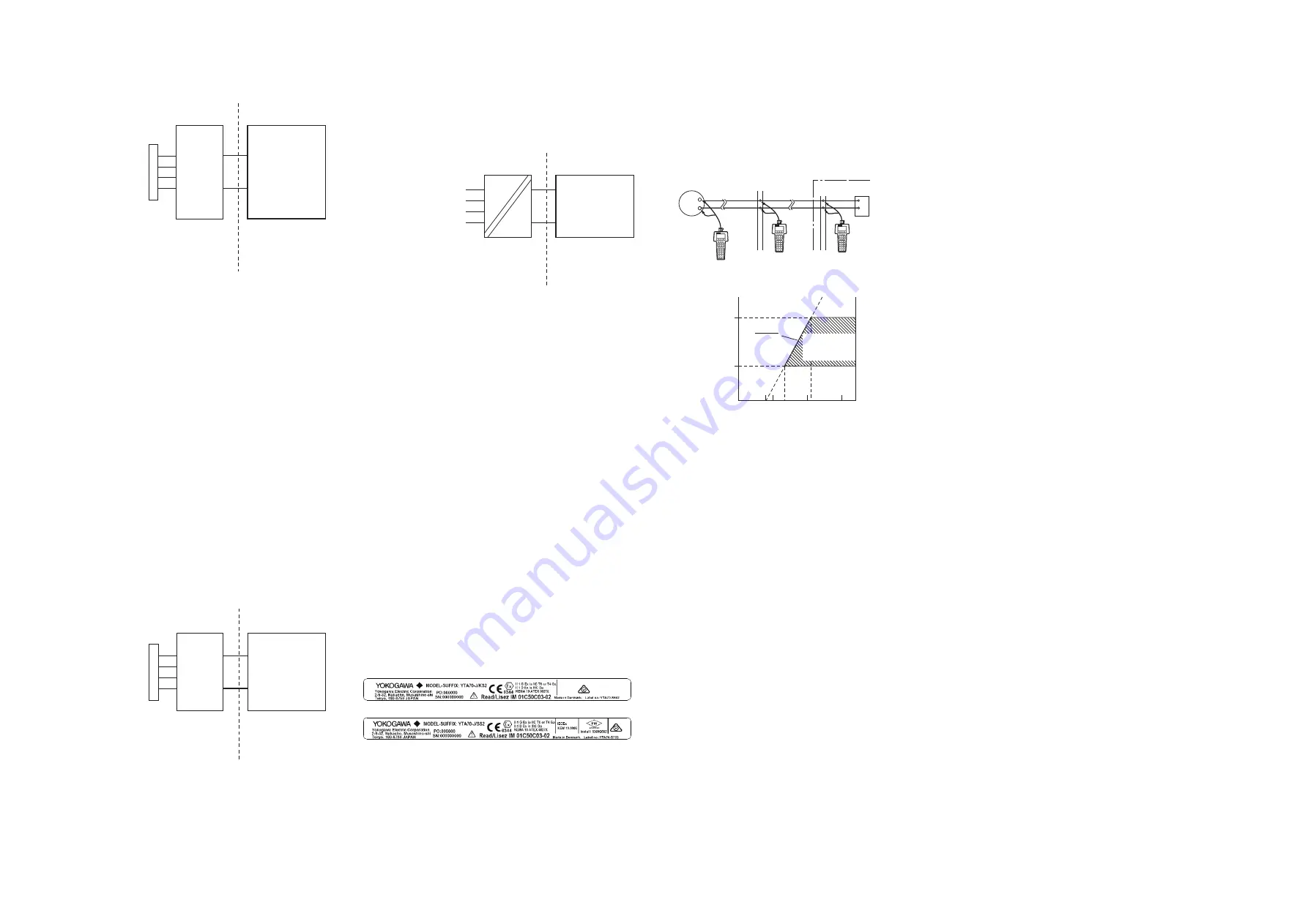
[Connection]
HART
communicator
HART
communicator
HART
communicator
YTA70
Distributor
Control room
Terminal board
Relaying
terminals
F07E.ai
+
−
[Communication requirement]
(Ω)
Power supply voltage E (V DC)
600
250
R
8.0 13.8
21.8
External
load
resistance
E-8
0.0236
R=
Digital
Communication
range
F08E.ai
35.0
8.2 Switching HART Protocol Revision
HART protocol revision of the transmitter can be selectable from 5 or 7. The HART
protocol revision is set and shipped as specified in the order. To change the HART
protocol revision after shipment, follow the procedure shown below. Please note
that selecting HART 5 will change the model code of YTA70-J to YTA70-E on the
configuration tool.
1) Call up the parameter for protocol revision change.
Device setup -> Detailed setup -> Device information -> Revision numbers ->
Chng universal rev
2) Activate the “Chg universal rev” method.
3) Select OK for confirmation message screen twice.
4) Select a HART protocol revision 5 or 7.
5) Enter a write protect password. The default password is “********”, eight
asterisks.
6) The device will automatically restarts with a new HART protocol revision.
Restart the HART configuration tool for parameter settings.