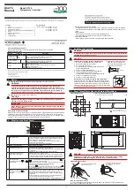


IM 05C01E02-01E 4th Edition Mar. 14, 2016-00
4
■
Alarm Function List
Alarm type
Action
“Opn” and “Cls” indicate that the relay
contact is opened and closed; “(on)” and
“(off)” indicate that the lamp is on and off;
and white triangles indicate temperature
control setpoints.
Alarm
type code
Alarm type
Action
“Opn” and “Cls” indicate that the relay
contact is opened and closed; “(on)” and
“(off)” indicate that the lamp is on and off;
and white triangles indicate temperature
control setpoints.
Alarm
type code
Closed
contact
during
alarm
Open
contact
during
alarm
Closed
contact
during
alarm
Open
contact
during
alarm
No alarm
OFF
De-
energized
on deviation
low limit
Hysteresis
Temperature setpoint
Deviation setting
Measured value
Opn (on)
Cls (off)
6
16
(See
note.)
PV
high limit
Hysteresis
Alarm setting
Measured value
Opn (off)
Cls (on)
1
11
(See
note.)
PV
low limit
Hysteresis
Alarm setting
Measured value
Opn (off)
Cls (on)
2
12
(See
note.)
Deviation
high and
low limit
Hysteresis
Hysteresis
Temperature setpoint
Deviation setting
Measured value
Cls
(on)
Opn
(off)
Cls
(on)
7
17
(See
note.)
Deviation
high limit
Opn (off)
Hysteresis
Cls (on)
Measured value
Temperature setpoint
Deviation setting
3
13
(See
note.)
Deviation
within
high- and
-low-limit
Hysteresis
Hysteresis
Temperature setpoint
Measured value
Opn (off)
Opn (off)
Cls (on)
Deviation setting
8
18
(See
note.)
Deviation
low limit
Cls (on)
Hysteresis
Opn (off)
Measured value
Temperature setpoint
Deviation setting
4
14
(See
note.)
De-
energized
on PV
high limit
Hysteresis
Opn (on)
Cls
(off)
Alarm setting
Measured value
9
19
(See
note.)
De-
energized
on deviation
high limit
Measured value
Temperature setpoint
Hysteresis
Deviation setting
Opn (on)
Cls (off)
5
15
(See
note.)
De-
energized
on PV
low limit
Hysteresis
Cls (off)
Opn (on)
Alarm setting
Measured value
10
20
(See
note.)
Fault
diagnostics
output
The contact is closed at input
burnout.
21
Heater
disconnection
alarm
The controller starts measuring the current from
the heater disconnection detector when 100
milliseconds have passed after turning on the
output.
Cls
(on)
Heater current
Alarm setting
Opn (off)
25
FAIL
output
The output contact is opened in the
following events:
• Program error • A/D converter error
• ROM error
• RJC error
• RAM error
• EEPROM error
• power failure
22
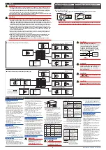
Note: The alarms numbered 1 to 10 have
no waiting action, while alarms 11
to 20 have a waiting action.
The waiting action turns off the
PV and deviation alarms that
occur from the start of the control
operation until a stable state is
reached.
Abnormal
Alarm output = ON
Normal
Low limit alarm
setpoint
In this area, the alarm output is turned
off even when a measured value falls
below the low limit alarm setpoint.
Time
Power-on
°C
Taken as
normal.
Waiting action
The waiting action is effective in the following cases where;
• The power is turned on
• SP is changed
• The alarm type is changed
■
Description of Parameters
This section describes the parameter functions specific to the UT130 temperature controllers.
(The functions described in other sections of this manual and the general functions are not
discussed.)
Parameter
Function
Parameter
Function
Control
mode
Select one from the following:
a. Dynamic auto tune control (SLF) (See note)
b. PID control (PID)
c. On/off control (ONF)
Note: Dynamic auto tune control is not available
for heating/cooling control.
Read the section below this table to find out more
about dynamic auto tune control.
PV input
bias
This function adds a bias value to the measured
input value, and the result is used for display and
control computation.
PV value inside the controller
measured input value
PV bias
+
=
This function is useful for carrying out fine
adjustment when the PV value is within the
required accuracy but it differs from the value
obtained by other equipment.
CTL
BS
Manual
reset
You can set this parameter only for control without
an integral action (when registered as CTL=PID
and I=OFF). The controller outputs the manual
reset (MR) value when PV=SP. For example, if
you set MR=50%, the controller outputs (OUT)
50% when PV=SP.
Maximum/
minimum
value of
target
setpoint
range
Using the SPH and SPL parameters, you can limit
the setting range of the target setpoint (SP) within
the measured input range.
This function prevents SP from being mistakenly
set at too large or too small a value (beyond the
setting range).
MR
SPH,
SPL
Cooling-side
gain
For heating/cooling control, you can set the ratio
between the cooling-side output and heating-side
output.
For example, if you set COL=2.0 and the heating-
side output is 10% at a certain deviation (SP-PV),
then the cooling-side output will be 20% when the
cooling-side also reaches that deviation.
COL
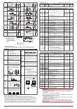
Hysteresis
for
alarm 1
and 2
The alarms are output as relay outputs. Since a
relay has a limited life, excessive on/off actions will
shorten the life of the alarm. To prevent this, you
can set a hysteresis to prevent excessive on/off
actions for both alarm 1 and alarm 2.
Deadband
You can only set a deadband for heating/cooling
control. In a positive deadband, there are neither
heating-side nor cooling-side outputs. In a
negative deadband, there are both heating-side
and cooling-side outputs, which overlap each
other.
HYS
HYS
ON
OFF
ON
OFF
Deadband
DB (+)
Deadband
DB (+)
0
SP
PV
100%
100
0
SP
100
PV
100%
Cooling
side
Heating
side
100%
0%
1. When the deadband of a heating/
cooling type is positive
(Proportional band [P] control)
2. When both the heating and cooling
sides are under on-off control
HY1,
HY2
SUPER
function
selection
The SUPER function is effective in the following
cases:
a. An overshoot must be suppressed.
b. The rise-up time needs to be shortened.
c. The load often varies.
d. SP is changed frequently.
Note 1: The SUPER function will not work
when on/off control is selected, or I or D
constants is set at OFF in PID control.
Note 2: For some types of systems, the SUPER
function may not be so useful. If this is the
case, turn off the function.
DB
SC
Hysteresis
for
on/off
control
For on/off control (CTL=ONF), you can set a
hysteresis band around the on/off point (SP) to
prevent chattering.
On/off point (SP)
Hysteresis band
ON
OFF
Priority of
PV/SP
display
Since the UT130 controller has a single data
indicator, you can give display priority to either
PV or SP. The data which has the priority will be
displayed on the data indicator upon power-on
or when the operating display is resumed from a
parameter setting display using the
key
(by pressing for at least 3 seconds).
To switch the display between PV and SP,
press the key.
Displays SP
Displays PV
SP display lamp is on.
HYS
Control
output
/ cooling-
side
control
output
cycle time ]
The cycle time is the period of on/off repetitions of
a relay or voltage pulse output in time proportional
PID control. The ratio of the ON time to the cycle
time is proportional to the control output value.
Cycle time
t ON
t OFF
C o o l i n g - s i d e
control output cycle
time has the same
functions.
*
CT
CTC
DSP
PV input
filter
This function should be used when the PV display
value may fluctuate greatly, for example, when the
measured input signal contains noise. The filter
is of the first-order lag type, and FL sets the time
constant. If a larger time constant is set, the filter
can remove more noise.
Input
2-seconds filter
10-seconds filter
FL
■
What is Dynamic Auto Tune Control?
Dynamic auto tune control is one of the features offered by the temperature controller.
When the controller is turned on or the measured input value (PV) starts “hunting”, this mode of
control monitors the behavior of the PV and/or OUT (control output value) to automatically determine
the optimum PID constants. This means that the PID constants may be changed automatically. If this
is not desirable for your system, operate the controller in the normal “PID control”.
If you want to automatically determine the PID constants at the initial startup of the controller, first
define the target setpoint (SP) and then turn the controller off once and then back on again. Do not
use dynamic auto tune control for a system where there is interference or continual disturbances.
■
Parameter Lists
Numbers in ( ) are the parmeter setpoints that apply when the
communication function is used. Ex. OFF(0), ON(1)
(1) Target Setpoint (SP)
Code
Name
Setting range and unit
Default
User setting
(SP value display)
Target
setpoint
Minimum value (SPL) to maximum value (SPH) of target
setpoint range
Unit: °C/°F
SPL
(2) Operating Parameters: Parameters changed rather frequently during operation.
Code
Name
Setting range and unit
Default
User setting
A1
Alarm 1
setpoint
■
PV alarm Unit: °C/°F
Setting range: minimum value to maximum value of
measured input range
■
Deviation alarm Unit: °C/°F
Setting range: –100 to 100% of the measured input range
span
■
Heater disconnection alarm Unit: A (ampere)
Setting range: OFF(0), 1 to 80
(can be set for the alarm 1 setpoint only)
Max. value of
measured input
range (PV alarm)
A2
Alarm 2
setpoint
Min. value of
measured input
range (PV alarm)
HC
Heater
disconnection
current
measured
value
“HC” is not a parameter to be set. The current value (0 to 80) of heater disconnection
detector is displayed. Unit: A (ampere)
Settings: When the display value is –––, the heater current is not being measured.
CTL
Control mode
ONF(0): On/off control
PID(1): PID control
SLF(2): Dynamic auto tune control (cannot be set for heating/
cooling control)
SLF(2) : standard
type;
PID(1) : heating/
cooling type
AT
Auto-tuning
OFF(0): Stop auto-tuning(AT)
ON(1): Start auto-tuning(AT)
OFF(0)
P
Proportional
band
1°C /°F to the temperature that corresponds to 100% of the
measured input range span
5% of measurd input
range span
I
Integral time 1 to 999 seconds;
OFF(0): no integral action
240 seconds
D
Derivative
time
1 to 999 seconds;
OFF(0): no derivative action
60 seconds
MR
Manual reset -19.9 to 99.9 % : Standard type
-100 to 100 % : Heating/cooling type
50.0% : standard
type; 0.0% : heating/
cooling type
COL
Cooling-side
gain
0.01 to 9.99 times
1.00 times
DB
Dead band
■
PID control Unit: °C/°F
Setting range: –(proportional band setting) to +(proportional
band setting)
■
On/off control Unit: °C/°F
Setting range: –50 to +50% of measured input range span
3.0% of measured
input range span
HYS
Hysteresis for
on/off control
0°C /°F to the temperature that corresponds to 100% of the
measured input range span
0.5% of measured
input range span
CT
Control
output cycle
time
1 to 240 seconds
30 seconds
CTC
Cooling-side
control output
cycle time
1 to 240 seconds
30 seconds
FL
PV input filter OFF(0), 1 to 120 seconds
OFF(0)
BS
PV input bias –100 to 100% of measured input range span
0% of measured
input range span
LOC
Key lock
0: No key lock
1: Prevents operations from being changed except for the
changing of SP in the operating display
2: Prevents all parameter changing operations
–1: Set “-1” to enter the setup parameter setting display. But
if “LOC=1 or 2” is already set, the parameter value can
not be changed by setting “LOC=-1” only. To change
the parameter value, set “LOC=0” at first (for disabling
keylock), then set “LOC=-1” once again.
0
(3) Setup Parameters: Parameters rarely changed in normal use after once having been set.
Code
Name
Setting range and unit
Default
User setting
IN
Measured
input type
1 to 7, 12, 13, 15 to 19, 31 to 37, 42, 43, 45 to 48 (See
measured input range code list.) OFF(0): No input
(If no input type is specified at the time of ordering, you must
set the input type.)
OFF(0), or the input
range code specified
with order
SPH
Maximum
value of
target
setpoint
range
(SPL+1°C) to the maximum value of the measured input
range; Unit: °C/°F
Maximum value
of measured input
range
SPL
Minimum
value of
target
setpoint
range
Minimum value of measured input range to (SPH–1°C)
Unit: °C/°F
Minimum value of
measured input
range
AL1
Alarm 1 type OFF(0), 1 to 22 (See the alarm function list.)
25 (for the heater disconnection alarm /HBA option only)
1
(PV high limit alarm)
AL2
Alarm 2 type
OFF(0), 1 to 22 (See the alarm function list.)
2
(PV low limit alarm)
HY1
Alarm 1
hysteresis
0 to 100% of measured input range span
Unit: °C/°F
0.5% of measured
input range span
HY2
Alarm 2
hysteresis
SC
SUPER
function
ON(1): Uses the SUPER function
OFF(0): Does not use SUPER function
Note: Not displayed when on/off control
OFF(0)
DR
Direct/
reverse
action
0: Reverse action
1: Direct action
Note: Not displayed for heating/cooling type
0
DSP
Priority of PV/
SP display
0: Displays PV
1: Displays target setpoint (SP)
0
PSL
Protocol
selection
0: PC-link communication
1: PC-link communication with sum check
2: Ladder communication
3: MODBUS in ASCII mode
4: MODBUS in RTU mode
0
ADR
Controller
address
1 to 99
However, the number of controllers that can be connected per
host device is 31 at the maximum.
1
BPS
Baud rate
2.4(0): 2400 bps
4.8(1): 4800 bps
9.6(2): 9600 bps
9.6(2)
PRI
Parity
NON(0): Disabled
EVN(1): Even parity
ODD(2): Odd parity
EVN(1)
STP
Stop bit
1 or 2 bits
1 bit
DLN
Data length
7 or 8 bits
• 8 bits when ladder, MODBUS (RTU)
• 7 bits when MODBUS (ASCII)
8 bits
IMPORTANT
To use dynamic auto tune control,
(1) be sure to turn on the final control element, such as a heater, before starting the
control, and
(2) make sure the controlled loop is a closed loop.
If you do not follow these precautions, improper PID constants may be written into the
controller. If this occurs, carry out the following:
• Set the parameter CTL at PID.
• Set the PID constants at the factory-set defaults (P = (upper range-limit - lower range-
limit) × 5%; I = 240 sec.; and D = 60 sec.)
• Set the parameter CTL at SLF.
If the control still doesn’t work properly, stop using the dynamic auto tune control
function. Change the parameter CTL setting to PID and execute auto-tuning to obtain
the PID constants.


