IM 701210-07E
37
SIMPLE/ENHANCED
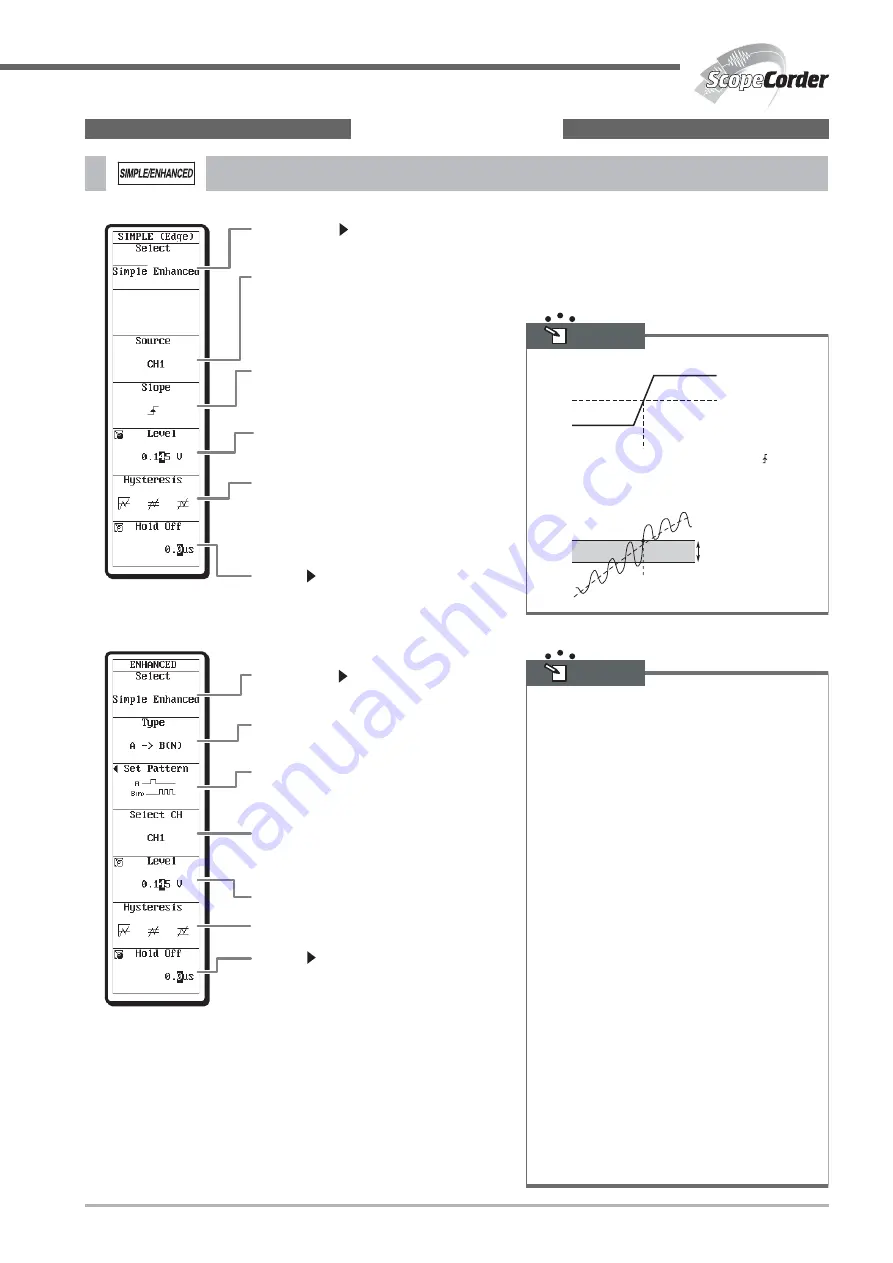
Trigger type
Chapter 6
Select simple trigger.
Trigger source
Select the trigger source from the input signal
(CH1 to CH16, LOGIC A, or LOGIC B, DSP1
to DSP6 (/G3 option)), external input signal
(Ext), power supply signal (Line), or time.
Trigger slope
Select the trigger slope from rising, falling,
and both rising and falling.
Trigger level
Set the level at which the trigger slope is to pass.
Trigger hysteresis
Select the hysteresis width, which is used set a
trigger level width to prevent triggers from
being activated on small changes in the trigger
source signal.
Hold off
Section 6.4
Set the time during which the trigger detection
operation is temporarily paused.
Trigger Slope and Trigger Level
Trigger Hysteresis
Note
Trigger level
When the trigger slope is set to rising ( ),
a trigger is activated here.
A trigger is activated here.
Hysteresis width
Enhanced Trigger Types
• A
→
B(N)
A trigger is activated the Nth time condition B becomes
true after condition A has become true.
• A Delay B
This function activates a trigger the first time condition B
becomes true after condition A has become true and the
preset time has elapsed.
• Edge
on
A
A trigger is activated when an edge trigger is detected on any
of the channels set to edge trigger while condition A is true.
• OR
A trigger is activated when any of the channels set to
edge trigger meets the condition.
• B > Time, B < Time, B TimeOut
A trigger is activated on the falling or rising edge of the
pulse when the pulse width (width over which condition
B is met) exceeds (or drops below) the preset time. In
the case of a Time out trigger, a trigger is activated when
the preset time elapses.
• Period
A trigger is activated by measuring the pulse period
(period from the time condition T is met to the next time
when condition T is met).
• Window
A certain voltage range (window) is set and a trigger is
activated when the trigger source level enters this voltage
range (IN) or exits from this voltage range (OUT).
• Wave
Window
Trigger for monitoring the power supply waveforms. It
detects abnormalities in the power supply (disruption,
sag, serge, frequency fluctuation, and voltage drop).
Applicable waveforms are AC waveforms whose
frequency is between 40 to 1000 Hz. A trigger is
activated when the waveform deviates from the reference
waveform (see page 10 in this guide).
Note
• The following figure shows the menu that appears when the trigger type is set to simple trigger.
Trigger type
Chapter 6
Select enhanced trigger.
Enhanced trigger type
Select the enhanced trigger type.
Set the pattern
Set the signal pattern used to activate the
trigger according to the selected trigger type.
Trigger level setting channel
Select the channel on which the trigger level is
to be set.
Trigger level
Trigger hysteresis
Hold off
Section 6.4
• The following figure shows the menu that appears when the trigger type is set to enhanced trigger.
Содержание ScopeCorder DL750P
Страница 1: ...ScopeCorder IM 701210 07E 3rd Edition...
Страница 60: ...IM 701210 07E 59 MEMO...
Страница 61: ...IM 701210 07E 60 MEMO...


