1-11
IM 253710-01E
Functions
1
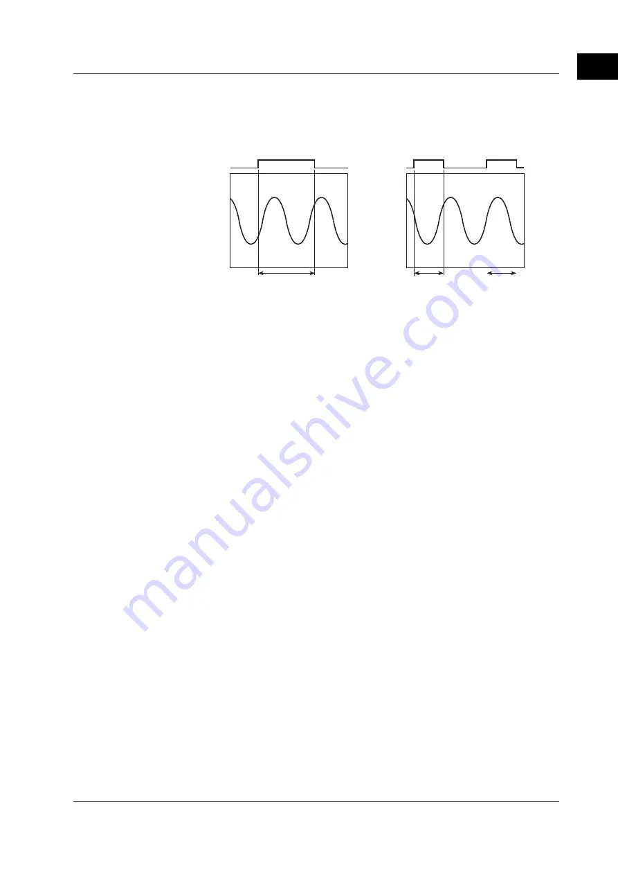
• External trigger setting
The measurement/computation period is set to the first period of time in which the
signal applied to the external trigger input connector is in the specified Hi or Lo
condition.
Measurement/
computation
period
Measurement/
computation
period
External trigger
condition
This section is not
considered for
measurement or
computation
During the harmonic measurement mode
Cursor setting is the only method available to select the period. The numerical data
are measured or computed from the sampled data in the specified period.
The period is 8192 sampled points between the vertical cursors placed on the screen.
You can set the measurement/computation period while viewing the displayed
waveform and moving the cursor.
Wiring Method «For procedures, see section 5.2.»
The wiring method is the method by which the signals that are input to each element are
combined. Different selections are possible depending on the number of elements that
have power measurement modules installed. In some cases, only one type of wiring
method can be selected, while in other cases, two types of wiring methods can be
selected. The following five wiring methods are available.
1P2W (single-phase two-wire), 1P3W (single-phase three-wire), 3P3W (three-phase
three-wire), 3V3A (three-voltage, three-current), 3P4W (three-phase four-wire)
When determining the
Σ
functions such as voltage, current, active power, apparent
power, reactive power, power factor, and phase difference, how the elements and
numerical data are combined varies depending on the wiring method. For details
pertaining to the relationship between the wiring method and
Σ
functions, see Appendix 2.
Number of Displayed Digits «For procedures, see section 8.1.»
The maximum number of displayed digits (highest display resolution) for the various
items such as voltage, current, active power, apparent power, reactive power, and power
factor can be set to five or six digits. However, the actual number of displayed digits may
sometimes be smaller than the specified number depending on the combinations of the
voltage and current ranges or the carry-over operation. For details, see chapter 16.
1.2 Measurement Modes and Measurement/Computation Periods


