background image

IM 04P01B01-01E 

1-14

For the procedure to set the functions, see section 1.10, “Function Setup Guide.”

Trend Recording

The measured values are printed within a width of 100 mm.

Recording Method (Pen Model)

•  The measured value is updated every scan interval and continuously recorded.
• The recording colors in order from channel 01 are red, green, blue, and violet.

Recording Method (Dot Model)

•  The most recent measured value is recorded with a dot every dot printing interval. The 

dot printing interval is in the range of 10 s to 90 s. There are two recording methods 
from which you can select. One method automatically adjusts the dot printing interval 
according to the chart speed so that the dots do not overlap. The other method 
records at the fastest dot printing interval at all times.

•  The recording colors in order from channel 01 are purple, red, green, blue, brown, and 

black. The recording color of each channel can be changed among these six colors.

•  For each channel, trend recording can be enabled or disabled.

<Related Topics>   

Setting the trend recording interval: Section 6.1 
Changing the recording color: Section 7.5 
Enabling/Disabling trend recording for each channel: Section 6.6

Chart Speed

On the pen model, the chart speed can be selected from 82 settings in the range of 5 to 
12000 mm/h.
On the dot model, the chart speed can be set in the range of 1 to 1500 mm/h in 1-mm 
steps.
The default setting is 20 mm/h.

<Related Topics>  

Setting the chart speed: Section 5.4
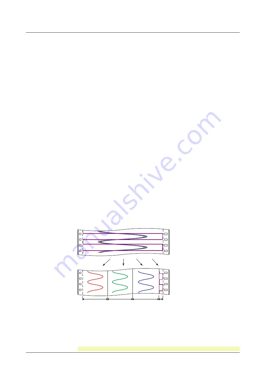
Zone Recording

A recording zone is assigned to each channel. This function is useful such when the 
recording results overlap making them difficult to be viewed.


Zone 1

Zone 2

Zone 3

Zone 4

<Related Topics>  

Setting the zone recording: Section 6.4

1.4  Recording

Содержание mR10000 436101

Страница 1: ...User s Manual Model 436101 436102 436103 436104 436106 µR10000 Recorder IM 04P01B01 01E 8th Edition ...

Страница 2: ......

Страница 3: ...nd any errors please contact your nearest YOKOGAWA dealer as listed on the back cover of this manual Copying or reproducing all or any part of the contents of this manual without the permission of Yokogawa Electric Corporation is strictly prohibited The TCP IP software of this product and the document concerning the TCP IP software have been developed created by YOKOGAWA based on the BSD Networkin...

Страница 4: ...2 5 1 3x Added Customized menu Section 1 9 Added Modbus register 40301 to 40348 Communication manual BT1 Added Header printout Section 1 4 1 4x EM1 Added SD memory card IM 04P01B01 03E Checking the Version Number You can check the version number on the System display The System display cannot be shown at the factory default condition First register the System display to the display screen Procedur...

Страница 5: ...to the instrument the operator must refer to the explanation in the manual Protective ground terminal AC DC High temperature To avoid injury caused by hot surface do not touch locations where this symbol appears For the protection and safe use of the product and the system controlled by it be sure to follow the instructions and precautions on safety that are stated in this manual whenever you hand...

Страница 6: ...External Connection Connect the protective grounding before connecting to the item under measurement or to an external control unit Damage to the Protective Structure Operating the recorder in a manner not described in this manual may damage its protective structure Portable Type H5x Option Use the Correct Power Supply Ensure that the power supply is within the maximum rated voltage range of the p...

Страница 7: ...ng this product except those stated in the WARRANTY that is provided separately Use the software on a single PC You must purchase another copy of the software if you are to use the software on another PC Copying the software for any purposes other than backup is strictly prohibited Please store the original media containing the software in a safe place Reverse engineering such as decompiling of th...

Страница 8: ...d input terminal 4 H3 Non glare door glass H5D Portable type Power cord UL CSA st d 7 H5F Portable type Power cord VDE st d 7 H5R Portable type Power cord AS st d 7 H5J Portable type Power cord BS st d 7 H5H Portable type Power cord GB st d 7 M1 Mathematical function N1 Cu10 Cu25 RTD input N2 3 legs isolated RTD 4 5 N3 Expansion inputs 6 P1 24 VDC AC power supply 7 R1 Remote control 5 points CC1 C...

Страница 9: ...l code H5F is specified Maximum rated power voltage 250 V A1024WD Provided when optional code H5R is specified Maximum rated power voltage 250 V A1023WD Provided when optional code H5J is specified Maximum rated power voltage 250 V A1064WD Provided when optional code H5H is specified Maximum rated power voltage 250 V Item 1 Pen 2 Pen 3 Pen 4 Pen Dot Printing Z fold chart paper 1 1 1 1 1 Ribbon cas...

Страница 10: ...Violet B9902AQ 1 3 pcs Plotter pen Purple B9902AR 1 3 pcs Mounting bracket B9900BX 2 Shunt resistor for the screw terminal standard 415920 1 250 Ω 0 1 415921 1 100 Ω 0 1 415922 1 10 Ω 0 1 Shunt resistor for the clamped input terminal H2 438920 1 250 Ω 0 1 438921 1 100 Ω 0 1 438922 1 10 Ω 0 1 SD memory card 773001 1 1 GB Software Sold Separately Item Model Note Configuration software RXA10 01 RXA10...

Страница 11: ...nger on the tab at the lower left of the display and open the display Display Tab on the display Open Open Remove all packing materials Pen Model Hinge Dot Model Hinge CAUTION To protect the hinges do not apply vertical force on the display Checking the Contents of the Package ...

Страница 12: ...cribes the setup operations for convenient functions such as how to assign tags to channels and how to set message strings that are to be printed 7 Setup Operations for Changing Adding Functions Basic Setting Mode Describes the setup operations for changing or adding functions such as setting the recorder to detect sensor burnouts and changing the contents that are printed on the chart paper 8 Set...

Страница 13: ... to prevent such occurrences Calls attentions to actions or conditions that could cause light injury to the user or damage to the instrument or user s data and precautions that can be taken to prevent such occurrences Calls attention to information that is important for proper operation of the instrument Note Subheadings On pages that describe the operating procedures in Chapter 3 through 9 the fo...

Страница 14: ...Blank ...

Страница 15: ...ng 2 11 2 6 Turning ON OFF the Power Switch 2 13 Chapter 3 Names of Parts and Run Operations 3 1 Names of Parts 3 1 3 2 Installing or Replacing the Chart Paper 3 4 3 3 Installing Replacing Felt Pens or Plotter Pen Pen Model 3 7 3 4 Installing Replacing the Ribbon Cassette Dot Model 3 9 3 5 Starting Stopping the Recording 3 11 3 6 Switching the Display Screen 3 12 3 7 Printing Measured Values Manua...

Страница 16: ... Setting the Burnout Detection Function of Thermocouples 7 5 7 4 Setting the RJC Function on Channels Set to TC Input 7 6 7 5 Changing the Channel Recording Color Dot Model 7 8 7 6 Recording by Compensating for the Pen Offset along the Time Axis Pen Model 7 9 7 7 Turning Printouts ON OFF Selecting the Channel Tag Printout and Turning ON OFF the Channel No Alarm Recording Start New Chart Speed Scal...

Страница 17: ...Channel Recording Color Dot Model 9 23 9 14 Changing the Channel Assignments of Recording Pens Pen Model 9 24 9 15 Changing the Type of Report Data Printed in Periodic Printout 9 25 9 16 Setting the Bar Graph Display Mode 9 27 9 17 Setting the Procedure Taken When the Computed Result Is in Error 9 28 Chapter 10 Troubleshooting 10 1 A List of Error Messages 10 1 10 2 Troubleshooting Flow Charts 10 ...

Страница 18: ...Blank ...

Страница 19: ...ccurrence release and predefined messages Also the recorder settings can be printed Internal Light A light is provided for easier viewing of the recording area of the chart paper Display Measured values can be displayed numerically or using bar graphs on the large display Also alarm status and chart speed can be displayed Communication Function Using the Ethernet communication interface C7 option ...

Страница 20: ...sed as measured values Also the low cut function input less than 0 is fixed to 0 scale left value can be used Current Input A shunt resistor is attached to the input terminal The current signal is converted to a voltage signal and measured The measurable range is the range equivalent to the DC voltage range indicated above after converting the current to the voltage signal Note Three types of shun...

Страница 21: ...els set to scaling or square root computation cannot be designated Scaling The input values are scaled to values in the appropriate unit to be used as measured values 0 V 100 0 C 10 V 300 0 C Measured value Input value Square Root Computation When the input type is DC voltage the square root of the input value is calculated the result is scaled to a value in the appropriate unit and used as the me...

Страница 22: ... value B A Scale value Calibration point Correction using absolute values Measured value A Correction value B A1 A2 A3 A4 A5 Related Topics Setting the calibration correction function Sections 7 15 7 23 and 6 13 Burnout Detection of Thermocouples This function makes the recording go off the scale to the right or left when the thermocouple burns out while measuring temperature with a thermocouple T...

Страница 23: ...ction can be set for each measurement channel However it does not operate on channels set to ON OFF input Filter Pen Model The filter is a low pass filter The time constant can be set to 2 s 5 s or 10 s 63 2 of the output value 2 5 10 s time constant the time it takes to reach 63 2 of the output value Output response curve when using the filter Input Filter result output for a step input Moving Av...

Страница 24: ...D Converter Pen model Select 16 7 ms 60 Hz 20 ms 50 Hz or Auto Dot model Select 16 7 ms 60 Hz 20 ms 50 Hz 100 ms or Auto If Auto is selected the recorder detects the power supply frequency and automatically selects 16 7 ms or 20 ms If Auto is specified when using the 24 VDC power supply on a recorder with the 24 VDC AC power supply P1 option the integration time is fixed to 20 ms 50 Hz Because 100...

Страница 25: ...erence High Limit Alarm h An alarm occurs when the difference in the input values of two channels is greater than or equal to the specified value Difference Low Limit Alarm l An alarm occurs when the difference in the input values of two channels is less than or equal to the specified value Can be specified on channels set to delta computation High Limit on Rate of Change Alarm R The rate of chang...

Страница 26: ...alls below the alarm value at time X4 and the alarm is released Note The alarm detection operation is reset when a power failure occurs The operation restarts after the power recovers If the alarm value is changed while a delay alarm is occurring the alarm is released if the new alarm value does not meet the alarm condition Alarm Hysteresis Hysteresis can be specified to the values for activating ...

Страница 27: ...ording The alarm occurrence release can be recorded on the chart paper See section 1 4 Alarm Output Relay A1 A2 and A3 Options Contact signals can be generated from alarm output relays when alarms occur The number of output relays is 2 A1 4 A2 or 6 A3 The alarm output relays are denoted as I01 to I06 on the recorder The following functions can be assigned to the alarm output relay Diagnosis Output...

Страница 28: ... I03 I01 and I02 for the A1 option By default the reflash alarm is disabled Alarm Alarm output relay Reflash alarm ON Alarm output relay Reflash alarm OFF Channel 1 Channel 3 Channel 2 Approx 500 ms Approx 500 ms Note If the reflash alarm is enabled I01 to I03 are set to reflash alarm operation In this case I01 to I03 are set to OR operation and non hold operation regardless of the settings specif...

Страница 29: ...tion Specifying AND produces no effect If diagnosis output is enabled I01 is set to diagnosis output Specifying AND produces no effect Related Topics Setting the AND operation Section 7 1 Energized De energized Operation of Alarm Output Relays You can select whether the alarm output relay is energized or de energized when an alarm occurs If de energized is selected the status of the alarm output r...

Страница 30: ...ACK Alarm ACK Alarm ACK or or Hold Non hold Activated Released Note If the reflash alarm is enabled I01 to I03 are fixed to non hold operation Specifying Hold produces no effect If diagnosis output is enabled I01 is fixed to non hold operation Specifying Hold produces no effect Related Topics Setting the non hold hold operation of alarm output relays Section 7 1 Alarm ACK Operation The alarm ackno...

Страница 31: ...apable of recording the measured values with pens or dots trend recording as well as various other types of information Recording Example on the Pen Model Recording Example on the Dot Model The recording examples may appear differently from the actual recording as a result of functional improvements made on the recorder after this manual was written Related Topics Starting Stopping recording Secti...

Страница 32: ... interval at all times The recording colors in order from channel 01 are purple red green blue brown and black The recording color of each channel can be changed among these six colors For each channel trend recording can be enabled or disabled Related Topics Setting the trend recording interval Section 6 1 Changing the recording color Section 7 5 Enabling Disabling trend recording for each channe...

Страница 33: ... 3 pen and 4 pen recorders there are offsets along the time axis phase difference between the pens This offset is corrected when pen offset compensation is used Same time Below is an explanation for the 2 pen model The recording of these two pens are offset by an amount of phase P If pen offset compensation is enabled the measured values of pen 1 are stored in the memory and recorded when the char...

Страница 34: ... a mark that indicates the position of the date time on the chart paper Time tick cancel mark An exclamation point is printed when the periodic printout time tick was not printed at the correct position Channel number or tag printout Channel numbers or tags can be printed Related Topics Switching between channel number printout and tag printout Section 7 7 Setting the periodic printout interval re...

Страница 35: ...d or disabled By default the channel printout is enabled Characters may become discolored or the ribbon may brush against the paper due to the warping of the ink ribbon or the like during a digital printout These do not occur during analog recording Digital printout type periodic printout alarm message printout channel printout Related Topics Switching between channel number printout and tag print...

Страница 36: ...ge Periodic Printout Measured values and other items are printed at the preset interval Printout is not performed when the chart speed is as follows Pen model Less than or equal to 9 mm h or greater than or equal to 1600 mm h Dot model 9 mm h or less 101 mm h or greater Printout Contents for details see appendix 1 Date time time ticks marks that indicate the positions of the date time on the chart...

Страница 37: ...ted A buffer overflow mark is printed when there are messages that cannot be printed because the buffer is full The time printout format can be selected New Chart Speed Printout Printout is not performed when the chart speed is as follows Pen model 1600 mm h or higher dot model 101 mm h or higher When the chart speed is changed the time tick dot model the date time of change and the new chart spee...

Страница 38: ...ut is complete List printout contains Setting Mode settings such as the input range and alarm for each channel Setup List contains Basic Setting Mode settings such as the alarm output relay operation and printout method Printout Example of List on the Pen Model The printout examples may appear differently from the actual printout as a result of functional improvements made on the recorder after th...

Страница 39: ...ions see section 1 10 Function Setup Guide 1 2 3 4 5 6 7 8 9 10 11 12 App Index Printout Example of List on the Dot Model The printout examples may appear differently from the actual printout as a result of functional improvements made on the recorder after this manual was written 1 4 Recording ...

Страница 40: ...rom the actual printout as a result of functional improvements Start Printout and End printout When recording starts Start printout or Start printout 2 prints Also when recording stops End printout or End printout 2 prints Printout Operation Description Notes Comment Prints 32 characters x 5 lines or less Batch name Can be displayed in the main display Batch number Prints up to 26 characters Lot n...

Страница 41: ...neous values are printed out together Up to 5 messages of 35 characters can be entered Messages are printed out in the order in which they are set Message strings set with the standard function are specified as the first n number of characters from the start of the string If a number of characters is specified more than once the first instance is n number of characters from the start of the string...

Страница 42: ...F when the alarm is released If the alarm indication is set to hold operation the indicator blinks when an alarm occurs When alarm ACK operation is performed the indicator turns ON or OFF MATH This indicator turns ON when computation on the computation function M1 option is started and turns OFF when stopped KEYLOCK This indicator turns ON when key lock is enabled and turns OFF when disabled CHART...

Страница 43: ...rement channel Symbol indicating an alarm Computation channel Channel on which an alarm is occurring Channel on which an alarm is not occurring Channel on which an alarm is not set Date Time and Chart Speed The date format can be specified see page 1 19 Date Chart speed Time Aug 31 2005 12000 11 26 37 mm h Status Display Remaining amount of chart paper is less than approx 2 cm F1 option Alarm stat...

Страница 44: ... Determines the common logarithm y log10x Exponent EXP Determines the exponent y e x Relational computation LT LE GT GE EQ NE Determines or of two elements and outputs 0 or 1 Logical computation AND OR XOR NOT Determines the AND logical product OR logical sum XOR exclusive logical sum of two elements NOT negation of an element and outputs 0 or 1 TLOG computation TLOG SUM TLOG MAX TLOG MIN TLOG AVE...

Страница 45: ...nits For example if the measured value of channel 01 is 20 mV and the measured value of channel 02 is 20 V the computed result of 01 02 is 40 Recording Computation Channels Trend Recording Trend recording is possible by setting the recording span for each computation channel The recording span of computation channels can be set in the range of 9999999 to 99999999 excluding the decimal Zone recordi...

Страница 46: ...ng using the TLOG timer see appendix 1 Related Topics Setting the periodic printout Sections 7 8 9 6 and 9 15 Setting the printout using the TLOG timer Sections 9 6 and 9 12 Alarms Up to 4 alarms can be assigned to each computation channel The alarm types are high limit alarm H low limit alarm L delay high limit alarm T and delay low limit alarm t Hysteresis can be specified to the values for acti...

Страница 47: ...when a CPU failure occurs Therefore relay output is carried out also when the power is turned OFF including a power failure This relay behavior cannot be changed FAIL Relay Output NO C NC Normal NO C NC Failure NO C NC Power OFF NO Normally Opened C Common NC Normally Closed Chart End Output When the remaining amount of chart paper falls to approximately 2 cm recording is stopped and the relay con...

Страница 48: ...the secondary chart speed while a level signal is applied to the terminal The secondary chart speed is set in advance Message 1 Printout to Message 5 Printout Remote input signal Trigger Prints message 1 to 5 on the chart paper Manual Printout Remote input signal Trigger Executes a manual printout Alarm ACK Remote input signal Trigger Alarm ACK is executed on all alarms that are occurring This is ...

Страница 49: ... on the status of the batch comment switching signal when recording is started stopped remotely When starting stopping by key operation performs Start printout and End printout Starting and Stopping Data Saving EM1 Option Remote input signal Edge rising start or falling stop Starts or stops data saving If data saving is in progress applying a rising edge signal produces no effect If data saving is...

Страница 50: ... the key lock function Section 3 13 Customize Menu The menu can be customized to display only the menus that you use version 1 31 or later Display only the items that you use on the FUNC key menu Display only the items that you use on the Setting mode menu Lock Basic Setting mode use a password to enter the mode The pen position adjustment pen model and dot printing position adjustment dot model c...

Страница 51: ...the date time when switching from the standard time to DST and the date time when switching back from DST to standard time When switching from standard time to DST the clock is set ahead by 1 hour When switching back from DST to standard time the clock is set back by 1 hour Related Topics Using the DST Section 6 16 Temperature Unit The temperature unit can be set to Celsius or Fahrenheit The setti...

Страница 52: ...setting Scaling Range span and scale 5 1 Use Range in Setting mode Unit 5 3 Use Unit in setting mode to set the unit after scaling Square Root Computation Range span and scale 5 1 Use Range in Setting mode Unit 5 3 Use Unit in setting mode to set the unit after scaling Low cut 7 15 Use Personalize Add function SQRT low cut in Basic Setting mode and select Use or Not If Use is selected set the Low ...

Страница 53: ...n Basic Setting mode to Hold and set Alarm Indicator to Hold Executing the alarm ACK operation 3 12 Use Func Alarm ACK in Operation mode to execute the release of the alarm output Set a hysteresis on the alarm occurrence release value of high limit alarm and low limit alarm Use Alarm Hysteresis in Basic Setting mode to set the hysteresis to be applied to the high limit alarm and low limit alarm of...

Страница 54: ... Alarm occurrence release printout Turn printout On Off 7 7 Use Print Alarm in Basic Setting mode to select whether to print the alarm occurrence and release print only the alarm occurrence or not print Time printout format 7 16 Use Personalize Time print Alarm in Basic Setting mode to set the time printout format when printing alarm occurrence release Recording Start Printout Turn printout On Off...

Страница 55: ...ight in Setting mode to set the internal light brightness 6 11 Computation function M1 option Item Description Reference Section Computing equation and recording span Use Math Formula in Setting mode to set the computing equation and recording span for each channel 9 2 TLOG computation If TLOG computation is selected use Math Timer in Basic Setting mode to set the timer operation 9 12 Use Math TLO...

Страница 56: ... 7 7 Common with measurement channels Periodic printout using TLOG timer dedicated to computation channels Computed value Scale Channel number or tag Recording color Timer number Mar 31 2004 15 50 TAG 00A 100 00UNITA B 1 0 200 00 200 00 TAG 00A UNITA RED TLOG1 Use Math Timer TLOG in Basic Setting mode to set the printout interval 9 12 Use Math Timer TLOG Print in Basic Setting mode to turn the pri...

Страница 57: ...rintout Use Batch in Basic Setting mode to set whether to use the start printout and end printout If Use is selected select a Lot No from 4 digits 6 digits or OFF 7 24 If Use is selected Use Batch Batch No in Setting mode to set the batch number 6 14 Use Batch Lot No in Setting mode to set the lot number Use Batch Detail Start End in Setting mode If Not is selected the Batch Lot No item in Basic S...

Страница 58: ...Blank ...

Страница 59: ...discoloring and deformation Keep electrically charged objects away from the recorder as this may cause malfunction Do not apply volatile chemicals to the door glass display panel keys etc Do not allow rubber and vinyl products to remain in contact with the recorder for long periods of time This may damage the recorder When not in use make sure to turn OFF the power switch If there are any symptoms...

Страница 60: ...ll the recorder horizontally However the recorder can be inclined up to 30 degrees backwards for panel mounting Note Condensation may occur if the recorder is moved to another place where both the ambient temperature and humidity are higher or if the temperature changes rapidly In addition measurement errors will result when using thermocouples In this case let the recorder adjust to the new envir...

Страница 61: ...according to the procedure below First attach the two mounting brackets and temporarily fasten the attachment screws Next fix the recorder in place by tightening the attachment screws with the appropriate torque When the recorder is approximately perpendicular to the panel as you fasten the screws press the mounting bracket against the case so that they are in contact with each other Screw tempora...

Страница 62: ...order is an INSTALLATION CATEGORY II product Precautions to Be Taken While Wiring Take the following precautions when wring the input signal cables It is recommended that crimp on lug with insulation sleeves designed for 4 mm screws be used when connecting the input output signal wires to the terminals However this does not apply clamped terminals H2 Crimp on lug with insulation sleeves for 4 mm s...

Страница 63: ...f a nearby fan turns ON or OFF Connecting the input wires in parallel with other devices can cause signal degradation affecting all connected devices If you need to make a parallel connection then Turn the burnout detection function OFF Ground the instruments to the same point Do not turn ON or OFF another instrument during operation This can have adverse effects on the other instruments RTDs cann...

Страница 64: ...mped input terminal Screw input terminal Philips screwdriver Flat blade screwdriver Crimp on lug with insulation sleeves Signal wire Signal wire Note Input signal wires of diameter less than or equal to 0 3 mm may not be secured firmly for clamped terminals H2 Fold over the conducting section of the wire for example to make sure that the wire is securely connected to the clamped terminal 3 Replace...

Страница 65: ...1 5V input and ON OFF input DC current input Leadwire resistance 10 Ω max wire The resistance of the three wires should be equal Example For a 4 to 20 mA input a shunt resistor of 250 Ω 0 1 can be used to convert to 1 5V input A B b Note RTD input terminals A and B on the dot model are isolated on each channel Terminal b is shorted internally across all channels However for 3 legs isolated RTDs N2...

Страница 66: ...to the recorder the terminals of the recorder and or the cable can be damaged In order to prevent tension from being applied directly on the terminals fasten all wiring cables to the rear of the mounting panel Use the following circuit voltage for the connection to the alarm FAIL status output terminal When the connection is to Mains Circuits primary AC power source circuits 150 V or less When the...

Страница 67: ...NC A3 NO C NC NO C NC NO C NC NO C NC NO C NC NO C NC A3 R1 F1 I01 I02 I03 I04 I05 I06 I01 I02 I03 I04 I05 I06 NO C NC NO C NC R1 CE FAIL 1 2 3 4 5 C 1 2 3 4 5 C R1 R1 F1 F1 R1 NO C NC NO C NC CE FAIL 1 2 3 4 5 C R1 F1 CE Chart end Shaded Arrangement of the communication interface C3 or C7 option terminals or connectors For details on wiring see the μR10000 μR20000 Communication Interface User s M...

Страница 68: ...erminal Remote Control Input Terminals 1 2 3 4 5 C 1 2 3 4 5 C C 1 to 5 Internal circuit Input type Photocoupler isolation Shared common C Allowable input voltage 5 VDC 5V 1 to 5 Remote control input terminals C Common Transistor input open collector Relay contact input voltage free contact C Negative side of the power supply Relay Contact Input Transistor Input Specifications Input signal Voltage...

Страница 69: ...C 60947 1 3 Connect a fuse in the power supply line Use a fuse approved by CSA for the use in North America or VDE for the use in Europe 2 A to 15 A other than P1 4 A to 15 A P1 option Do not add a switch or fuse to the ground line Portable Type H5x Option Ensure that the source voltage matches the rated power supply voltage of the instrument before connecting the power cord Connect the power cord...

Страница 70: ... than P1 P1 24 VDC AC power supply L N L N DC AC24V 3 Close the power supply terminal cover and secure it with the screw The proper torque for tightening the screws is 0 6 N m Portable Type H5x Option 1 Check that the power switch to the recorder is turned OFF 2 Connect the plug on the accessory power cord to the power supply connector on the rear panel 1 0 0 2 4 0 V 5 0 6 0 H z 4 0 V A M A X 3 En...

Страница 71: ...turn ON OFF the power switch of the recorder or another device during operation This can have adverse effects on the measured values If nothing is displayed when the power switch is turned ON turn OFF the power switch and check the points listed above one more time After checking the points turn ON the power switch again If the unit still does not work it is probably malfunctioning Contact your ne...

Страница 72: ...Blank ...

Страница 73: ...wer left and pull to open Mounting hole There is one hole on each of the top bottom left and right panels The hole is covered with a seal Pen model Dot model Display and key panel see the next page There is an internal light on the bottom section of the display and key panel It lights up the recording area of the chart paper Recording pen Records the measured value Plotter pen Prints various types...

Страница 74: ... Key Switches the setup item or the value Press this key while holding down the SHIFT key to switch the setup item or the value in reverse order LEFT RIGHT Key Moves the cursor to the right when entering a value or character Press this key while holding down the SHIFT key to move the cursor to the left SHIFT Key Used with the key key or the CHARACTER key ENTER Key Confirms the setup item or value ...

Страница 75: ...is where terminals or ports used by options such as alarm output relays and communication interface are installed Ethernet port C7 option Power terminal block The power terminal and protective ground terminal Portable Type H5x Option Carrying handle Feet 4 pieces 10 0 24 0V 50 6 0H z 40 VA M A X Protective ground terminal spare Power terminal With protective ground terminal attach the specified po...

Страница 76: ...ration Be sure to replace the chart paper ahead of time When attaching the chart cassette push it in until you hear the left and right stoppers click into place Recordings will be inaccurate if the chart cassette is not fixed in place with stoppers Loading the Chart Paper 1 Open the door If recording is in progress press the RCD key to stop the recording 2 Remove the chart cassette Gently pressing...

Страница 77: ...et Chart paper guide 4 Load the chart paper Riffle the chart thoroughly before loading Make sure that the sprocket teeth of the chart drives are properly engaged in the chart paper perforations Make sure not to load the chart paper backwards Z fold chart paper Sprocket teeth 5 Close the chart holder and close the chart paper guide Chart holder Chart paper guide The side with the long rectangular h...

Страница 78: ...ecorder and press the entire chart cassette into the recorder case Push in the chart cassette until it is fixed in place with stoppers Stopper Feeding the Chart Paper 7 Press the FEED key to assure that the chart moves two or more folds smoothly into the chart receiver If it moves unsteadily do the installing procedure again 3 2 Installing or Replacing the Chart Paper ...

Страница 79: ...ot to let the ink come in contact with the eyes mouth or skin If the ink enters the eyes or mouth immediately wash with water If the ink makes contact with your skin immediately wash with soap and water If you notice any abnormal symptoms immediately consult a doctor Replacing Felt Pens 1 Open the door If recording is in progress press the RCD key to stop the recording 2 Open the display and key p...

Страница 80: ...pen pen holder moves near the center position and the Pen exchange End appears Note When the pen moves a line is drawn on the chart paper 4 Replace the pen 5 Press the CH UP key The screen returns to the data display screen Replacing the Plotter Pen 1 Open the door If recording is in progress press the RCD key to stop the recording 2 Open the display and key panel section 3 Hold the plotter pen ca...

Страница 81: ... makes contact with your skin immediately wash with soap and water If you notice any abnormal symptoms immediately consult a doctor 1 Open the door If recording is in progress press the RCD key to stop the recording 2 Press the FUNC key 3 Press the DISP key several times to display R exchange Func R exchange 4 Press the CH UP key The printer carriage moves near the center position and R exchange E...

Страница 82: ...cult turn the ribbon feeding knob in the direc tion of the arrow to align the ribbon feeding shaft of the cassette with the ribbon feeding shaft hole of the holder Holder tab Hole for the ribbon feed shaft Cassette holder Ribbon feeding knob 8 Turn the ribbon feeding knob in the direction of the arrow a half turn or more to check that the ribbon is feeding properly If the ribbon is loose turn the ...

Страница 83: ...hart feed will not start even when pressing the RCD key if the chart paper is empty or almost out Insert new chart paper before pressing the RCD key Stopping the Recording While recording is in progress press the RCD key to stop the chart feed The word RECORD on the status display clears Feeding the Chart Paper Manually The chart paper is fed while the FEED key is held down Viewing the Recorded Re...

Страница 84: ...mputed values the displayed channel is automatically switched in ascending order The switching interval can be set to 1 s 2 s 3 s 4 s or 5 s Measurement channels set to Skip and computation channels set to OFF are not displayed Switching the Displayed Channel Using Keys If Manual switching is specified the channel switches each time the CH UP key is pressed in ascending order All channels are disp...

Страница 85: ... manual printout is executed trend recording is suspended However the recorder continues the measurement and alarm detection in the background When manual printout is complete trend recording resumes If an alarm occurs during the manual printout the alarm is printed after the trend recording resumes Aborting the Manual Printout The following procedure is for aborting the manual printout that is in...

Страница 86: ...st Start and then press the key The List printout starts The screen returns to the data display screen Print List Start Aborting the List Printout 1 Press the FUNC key 2 Press the key to select Print out and then press the key 3 Press the key to display List Stop and then press the key The List printout stops The screen returns to the data display screen Print List Stop Starting the Setup Printout...

Страница 87: ...ction can be used to prevent unneeded alarm printouts from being executed Procedure 1 Press the FUNC key 2 Press the key to select Buffer clear and then press the key Func Buffer clear 3 Press the key to select Alarm and then press the key The data in the alarm printout buffer is cleared The screen returns to the data dis play screen Buf clear Alarm When the key or key is pressed while holding dow...

Страница 88: ...e key to select Message and then press the key Func Message 3 Press the key to select message number and then press the key The message printout starts The screen returns to the data display screen Displays the preset message Message Message1 Clearing the Message Printout Buffer Messages waiting to be printed are temporarily stored in the buffer memory This operation clears the messages in the buf...

Страница 89: ...ured values in periodic printout Procedure Resetting the Report Data 1 Press the FUNC key 2 Press the key to select Periodic and then press the key Func Periodic 3 Press the key to select Reset and then press the key The report data is reset and the calculation of the report data starts again from that point The screen returns to the data display screen Log data Reset When the key or key is presse...

Страница 90: ...larm is released The alarm output is released when the alarm ACK operation is carried out When an alarm is occurring The alarm output is held even after the alarm ACK operation If the alarm ACK operation is carried out again after the alarm is released the alarm output is released Indication Status Display Blinks when an alarm occurs When the alarm is released The alarm indication turns OFF when t...

Страница 91: ...easing the Key Lock Note A password is required to release the key lock 1 Press the FUNC key 2 Press the key to select Keylock and then press the key 3 Enter the password for releasing the key lock The password values are shown with asterisks Press the key to increment the value Press the SHIFT key to decrement the value Press the key to move the cursor to the right Press SHIFT key to move the cur...

Страница 92: ...Blank ...

Страница 93: ...annels and the computing equation unit constant and TLOG setting of computation channels cannot be changed while computation M1 option is in progress The operations that can be carried out in this mode are described in chapter 5 and 6 Basic Setting Mode This mode is used to set the basic specifications of the recorder such as the thermocouple burnout detection function and the alarm output relay o...

Страница 94: ...red from Setting mode Hold down the MENU key for 3 seconds to enter Setting mode Next hold down both the DISP key and the FUNC key for 3 seconds The Basic Setting mode display appears The top and bottom lines are the setup item and comment respectively The section that is blinking in the setup item that you change In this manual the section that you change appears shaded The item to be controlled ...

Страница 95: ...u make a selection press the key The next screen appears When the Setting complete screen appears the changed item is applied 01 01 Channel Setting complete Using the ESC Key If you press the ESC MENU key the operation is cancelled and the display returns to a higher level menu In other words if you do not show the Setting Complete screen the changes you made up to that point are discarded Press t...

Страница 96: ... character is to be inserted Press the CHARACTER key or SHIFT CHARACTER key to show Ins DISP and then press the key A space for one character is inserted Enter the character Position to insert the character Display Ins DISP Unit ppm CHR Ins DISP Deleting a Character Use the key or SHIFT key to move the cursor to the character to be deleted Press the CHARACTER key or SHIFT CHARACTER key to show Del...

Страница 97: ...7 3 8 sections 3 9 3 10 section 3 13 section 3 11 section 3 4 Pen exchange End Pen exchange section 3 3 Math key FUNC With the SD memory card EM1 option Data save Data replay SD card Eject menu items are added Alarm ACK Alarm output release operation This operation is valid only when the alarm indication or relay output is set to hold operation Math Models with the Computation Function M1 Option S...

Страница 98: ... Default Values Pen exchange Pen Model Moves the recording pen to a position that is easily accessible for replacement on the pen model R exchange Dot Model Moves the printer carriage near the center position when replacing the ribbon cassette on the dot model ...

Страница 99: ...Light DST DST Start month Start day Start time End month End day End time mm h Tag Periodic are not displayed in the default condition To display these items settings must be changed in Basic Setting mode section 5 1 section 6 12 section 6 13 section 5 2 section 5 3 section 5 4 section 5 5 section 6 1 section 6 4 section 6 5 section 6 6 section 6 7 section 6 8 section 6 9 section 6 3 section 6 2 s...

Страница 100: ...n Register User Password Suffix_S P_Adj Pen No Value End End Timeout Duration Keep alive Host Level Suffix primary IP address Subnet mask Primary server Secondary server Gateway Suffix secondary Indicator Increase Decrease Hysteresis M_Hysteresis section 7 1 section 7 2 section 7 3 section 7 4 section 7 5 section 7 6 section 7 7 section 7 8 section 7 8 section 7 9 section 7 10 section 7 11 section...

Страница 101: ...type Alarm Relay On Off Off Alarm Relay No I01 to I06 I01 Unit CH 01 to 06 01 Unit Unit 6 characters or less Blank Chart Pen Model 82 types pen model 20 mm h Dot Model 1 to 1500 mm h dot model 20 mm h Clock Date Time Aux Trend Dot Model Auto Fix Auto Aux Zone CH 01 to 06 01 Aux Zone Left Right Within the recording span range mm Left 0 Right 100 Aux Partial CH 01 to 06 01 Aux Partial Partial On Off...

Страница 102: ...0D 0E 0F 0G 0J 0K 0M 0N 0P 0A Math Aux Print out Trend Dot Model On Off On Math Aux Print out Periodic On Off On Math Aux Tag CH 0A 0B 0C 0D 0E 0F 0G 0J 0K 0M 0N 0P 0A Math Aux Tag Tag 7 characters or less A to P Math Aux Alm delay T CH 0A 0B 0C 0D 0E 0F 0G 0J 0K 0M 0N 0P 0A Math Aux Alm delay T Duration 0 to 3600s 10s Batch BT1 option Batch Batch No 26 characters or less Blank Batch Lot No 0000 9...

Страница 103: ... On Off Off Print CH Tag CH Tag CH Print Channel Dot Model On Off On Print Alarm On1 On2 Off On1 Print Record On On Off Off Print Chart speed On Off On Print Scale On Off On Print Pen color Pen Model On Off On Print1 Periodic Auto Manual Auto Print1 Ref Time Hour 0 to 23 1 hour steps 00 00 Print1 Interval 10min 15min 20min 30min 1h 2h 3h 4h 6h 8h 12h 24h 1h Print1 Mode Inst Report Off Inst Print2 ...

Страница 104: ...ssage5 Priority R_RCD BT1 BatchCMT switch BT1 BatchCMT switch BT1 Data save On Off EM1 None M1 BT1 EM1 option Record On Off Math M1 option Math Timer TLOG Timer No 1 2 1 Math Timer TLOG Mode Off Relative Absolute Absolute Math Timer TLOG Interval Relative 10 min to 24 h 1 min steps 01 00 Math Timer TLOG Interval Absolute 10min 12min 15min 20min 30min 1h 2h 3h 4h 6h 8h 12h 24h 1h Math Timer TLOG Re...

Страница 105: ...On Calibration CC1 option Calibration CH 01 to 06 01 Calibration Mode Revise Value Abs Value Revise Value Calibration Point 2 to 16 2 Cust menu Cust menu Not Use Not Cust menu Password Numbers and spaces within 4 digits Blank Cust menu P_Adj On Off Off Select menu Set mode Range On Off On Select menu Set mode Bias On Off On Select menu Set mode Alarm On Off On Select menu Set mode Unit On Off On S...

Страница 106: ...M 04P01B01 01E 4 14 4 3 Menu Structure Settings and List of Default Values Setup Item Pen Dot Selectable Range or Selections Default Value P_Adj Pen No Pen Model 1 2 3 4 1 Store End End Store Abort Store ...

Страница 107: ...h Range shown on the screen 3 Set each item and press the key Use the key or SHIFT key to select values For the procedure on how to enter values or characters see section 4 2 If you press the ESC key in the middle of the operation the settings entered up to then are cancelled and the display returns to a higher level menu 4 When the Setting complete screen appears do either of the following Press ...

Страница 108: ...2012 0 F T 200 0 to 400 0 C 328 0 to 752 0 F N 0 0 to 1300 0 C 32 to 2372 F W 0 0 to 2315 0 C 32 to 4199 F L 200 0 to 900 0 C 328 0 to 1652 0 F U 200 0 to 400 0 C 328 0 to 752 0 F WRe 0 0 to 2400 0 C 32 to 4352 F RTD Range Type Selectable Span Range C Selectable Span Range F PT Pt100 200 0 to 600 0 C 328 0 to 1112 0 F JPT JPt100 200 0 to 550 0 C 328 0 to 1022 0 F RTD Range Type Selectable Span Ran...

Страница 109: ..._R 200 00 01 01 Channel Setting complete Description Scale Left Scale Right and Decimal Place Selectable range mantissa 20000 to 30000 Example The value in the range of 100 00 to 350 00 cannot be specified The mantissa of Scale_R is 35000 which exceeds the upper limit of 30000 Set in the range of 100 0 to 350 0 Decimal place XXXXX XXXX X XXX XX XX XXX X XXXX The decimal place is set using Scale_L ...

Страница 110: ...left and span right cannot be set to the same value Input Type Range Type Selectable Span Range DC voltage Volt 20 mV 20 00 to 20 00 mV 60 mV 60 00 to 60 00 mV 200 mV 200 0 to 200 0 mV 2 V 2 000 to 2 000 V 6 V 6 000 to 6 000 V 20 V 20 00 to 20 00 V 50 V 50 00 to 50 00 V Thermocouple TC R 1760 0 to 1760 0 C 3168 to 3168 F S 1760 0 to 1760 0 C 3168 to 3168 F B 1820 0 to 1820 0 C 3276 to 3276 F K 157...

Страница 111: ...he new setting takes effect First channel Last channel ESC Set Range CH 01 01 MOde DI Range Level Span_L 0 Span_R 1 01 01 Channel Setting complete Description Selectable Range Type Span Left and Span Right The range type span left and span right can be set in the range shown below Span left and span right cannot be set to the same value Range Type Selectable Span Values Level 0 Less than 2 4 V 1 2...

Страница 112: ...5 2 V Scale Left Scale Right and Decimal Place Selectable range mantissa 20000 to 30000 Example The value in the range of 100 00 to 350 00 cannot be specified The mantissa of Scale_R is 35000 which exceeds the upper limit of 30000 Set in the range of 100 0 to 350 0 Decimal place XXXXX XXXX X XXX XX XX XXX X XXXX The decimal place is set using Scale_L It cannot be set using Scale_R Example Change 0...

Страница 113: ...t the right span value Set the decimal place and left scale value Set the right scale value Turn On or Off the low cut function Set the low cut point 0 0 to 5 0 of the recording span 0 1 steps The new setting takes effect First channel Last channel ESC Set Range CH 01 01 Mode SQRT Range 2V Span_L 2 000 Span_R 2 000 Scale_L 0 00 Scale_R 200 00 Low cut Off Low cut point 0 0 01 01 Channel Setting com...

Страница 114: ...Selectable range of the low cut point 0 0 to 5 0 of the recording span Values below the low cut point is set to 0 scale left value of the recording span Note The displayable printable range of scale values is 19999 to 30000 excluding the decimal If the leftmost value of the scale is set to 20000 excluding the decimal and the low cut value is set to 20000 the value when the low cut function is appl...

Страница 115: ...are cancelled and the display returns to a higher level menu 4 When the Setting complete screen appears do either of the following Press the key to set other channels If you are done press the ESC key 5 Hold down the MENU key for 3 seconds to return to Operation mode Select the level number between 1 and 4 Select On to set the alarm When set to On the settings below can be entered Set the channel ...

Страница 116: ...t alarm t Delay low limit alarm Selectable only when the alarm delay function is enabled See section 7 15 Note On channels set to delta computation alarms can be detected on the values illustrated in the figure below Input value Measured value on the reference channel Alarm on a channel set to delta computation Alarm H L R r T and t Alarm h and l Measured value If high limit on rate of change alar...

Страница 117: ...value of the scale is set to 20000 excluding the decimal the alarm value of 20000 is invalid Set a value that is greater than or equal 19999 Difference High Limit Alarm Difference Low Limit Alarm Values in the measurable range can be specified Measurable range refers to Selectable Span Range in the table on page 5 4 High Limit on Rate of Change Alarm Low Limit on Rate of Change Alarm A value great...

Страница 118: ...ered up to then are cancelled and the display returns to a higher level menu 4 When the Setting complete screen appears do either of the following Press the key to set other channels If you are done press the ESC key 5 Hold down the MENU key for 3 seconds to return to Operation mode Set the unit Set the channel range The new setting takes effect First channel Last channel ESC Set Unit CH 01 01 Uni...

Страница 119: ... the Setting complete screen appears do either of the following To correct the setting press the key If you are done press the ESC key 5 Hold down the MENU key for 3 seconds to return to Operation mode Set the chart speed The new setting takes effect ESC Set Chart mm h 20 Chart speed Setting complete Explanation Chart Speed Pen Model The chart speed can be selected from 82 settings shown below Cha...

Страница 120: ... 4 When the Setting complete screen appears do either of the following To correct the setting press the key If you are done press the ESC key 5 Hold down the MENU key for 3 seconds to return to Operation mode Set the time day month year The new setting takes effect ESC Set Clock 04 02 17 10 39 47 Clock Setting complete Explanation Date Time The year is set with the lower two digits Values in the r...

Страница 121: ...o either of the following To correct the setting press the key If you are done press the ESC key 6 Hold down the MENU key for 3 seconds to return to Operation mode Select the trend recording interval mode The new setting takes effect ESC Set Aux Aux Trend Mode Auto Trend Interval Setting complete Explanation Mode Auto The trend recording interval is set according to the chart speed in the range of...

Страница 122: ...ate Auto Chart speed 23 mm h Number of recording channels 6 channels Scan interval 1 s A value that is less than or equal to 900 chart speed and that is the largest integer multiple of the scan interval 39 s Because this 39 s is within the range of the fastest 10 s to 90 s recording interval 39 0 s 6 1 Setting the Trend Recording Interval Dot Model ...

Страница 123: ...r values or characters see section 4 2 If you press the ESC key in the middle of the operation the settings entered up to then are cancelled and the display returns to a higher level menu 5 When the Setting complete screen appears do either of the following Press the key to set other channels If you are done press the ESC key 6 Hold down the MENU key for 3 seconds to return to Operation mode Set t...

Страница 124: ...settings entered up to then are cancelled and the display returns to a higher level menu 5 When the Setting complete screen appears do either of the following Press the key to set other channels If you are done press the ESC key 6 Hold down the MENU key for 3 seconds to return to Operation mode Set the channel range Set the number of samples of the moving average Moving average is not performed wh...

Страница 125: ... entered up to then are cancelled and the display returns to a higher level menu 5 When the Setting complete screen appears do either of the following Press the key to set other channels If you are done press the ESC key 6 Hold down the MENU key for 3 seconds to return to Operation mode Set the channel range Set the leftmost value of the recording zone Set the rightmost value of the recording zone...

Страница 126: ...g complete screen appears do either of the following Press the key to set other channels If you are done press the ESC key 6 Hold down the MENU key for 3 seconds to return to Operation mode Set the channel range Select On to use the partial expanded recording function Set the boundary position as a percentage where the recording span is assumed to be 100 Set the boundary value within the recording...

Страница 127: ...w to enter values or characters see section 4 2 If you press the ESC key in the middle of the operation the settings entered up to then are cancelled and the display returns to a higher level menu 5 When the Setting complete screen appears do either of the following Press the key to set other channels If you are done press the ESC key 6 Hold down the MENU key for 3 seconds to return to Operation m...

Страница 128: ...ings entered up to then are cancelled and the display returns to a higher level menu 5 When the Setting complete screen appears do either of the following Press the key to set other channels If you are done press the ESC key 6 Hold down the MENU key for 3 seconds to return to Operation mode Set the channel range Set the tag The new setting takes effect ESC First channel Last channel Set Aux Aux Ta...

Страница 129: ...cedure on how to enter values or characters see section 4 2 If you press the ESC key in the middle of the operation the settings entered up to then are cancelled and the display returns to a higher level menu 5 When the Setting complete screen appears do either of the following To correct the setting press the key If you are done press the ESC key 6 Hold down the MENU key for 3 seconds to return t...

Страница 130: ...se the key or SHIFT key to select values For the procedure on how to enter values or characters see section 4 2 If you press the ESC key in the middle of the operation the settings entered up to then are cancelled and the display returns to a higher level menu 5 When the Setting complete screen appears do either of the following To correct the setting press the key If you are done press the ESC ke...

Страница 131: ...d and the display returns to a higher level menu 5 When the Setting complete screen appears do either of the following Press the key to set other channels If you are done press the ESC key 6 Hold down the MENU key for 3 seconds to return to Operation mode Set the channel range Set the alarm delay time The new setting takes effect ESC First channel Last channel Set Aux Aux Alm delay T CH 01 01 Dura...

Страница 132: ...entered up to then are cancelled and the display returns to a higher level menu 5 When the Setting complete screen appears do either of the following To correct the setting press the key If you are done press the ESC key 6 Hold down the MENU key for 3 seconds to return to Operation mode Select the brightness of the display Select the brightness of the internal light The new setting takes effect ES...

Страница 133: ...er channels If you are done press the ESC key 5 Hold down the MENU key for 3 seconds to return to Operation mode Select whether to use the bias Set the bias value Set the channel range The new setting takes effect First channel Last channel ESC When Bias is On Set Bias CH 01 01 Bias Off Bias 0 000 01 01 Channel Setting complete Explanation Channel Range The only case when a bias can be set on mult...

Страница 134: ...press the ESC key in the middle of the operation the settings entered up to then are cancelled and the display returns to a higher level menu 4 When the Setting complete screen appears do either of the following Press the key to set other channels If you are done press the ESC key 5 Hold down the MENU key for 3 seconds to return to Operation mode Set Calibration CH 01 01CH Calibration Setting comp...

Страница 135: ... when using revise values A1 A2 A3 A16 A1 B1 A2 B2 A3 B3 A16 B16 A and B are within the measurable range or scaling range of the range type Within the scaling range 5 to 105 of the scale value or 20000 to 30000 the decimal place is the same as the setting for the scale value Setting range of measured and correction values when using absolute values A1 A2 A3 A16 B1 B2 B3 B16 A and B are within the ...

Страница 136: ...w to enter values or characters see section 4 2 If you press the ESC key in the middle of the operation the settings entered up to then are cancelled and the display returns to a higher level menu 4 When the Setting complete screen appears do either of the following To correct the setting the key If you are done press the ESC key 5 Hold down the MENU key for 3 seconds to return to Operation mode S...

Страница 137: ...SC Select Detail Selecting Printout On Off for the Batch Name Chart Speed and Date Time Set Batch Mode Start Detail Print Batch name On Chart speed On Batch print Setting complete Select Start End Start2 or End2 Select Print Select whether to printout batch number and lot number Select On or Off Select whether to printout chart speed Select On or Off The new setting takes effect Batch Detail Clock...

Страница 138: ...ect whether to eject the pen offset compensating data when recording stops Select On or Off POC speed C Speed Select the chart speed when ejecting the pen offset compensating data ESC Select Detail Explanation Batch No You can enter up to 26 characters The following are the characters that can be used Alphabet numbers symbols µ Ω 2 3 and space Lot No Enter using a 4 or 6 digit number Select which ...

Страница 139: ...d printout 2 is not performed When recording stop detection is performed option F1 recording and printout stop When chart paper is inserted the instrument operates as follows When detected during Start printout and recording Recording starts after Start printout When detected during End printout When stopped End printout End printout 2 is not performed Until Start printout Start printout 2 and End...

Страница 140: ... SHIFT key to select MSG format and then press the key 4 Set each item and press the key Use the key or SHIFT key to select values For the procedure on how to enter values or characters see section 4 2 If you press the ESC key in the middle of the operation the settings entered up to then are cancelled and the display returns to a higher level menu 5 When the Setting complete screen appears do eit...

Страница 141: ...ers M D H M Month Day Hour Minute 11 characters M D H M S Month Day Hour Minute Second 14 characters D M H M Day Month Hour Minute 11 characters D M H M S Day Month Hour Minute Second 14 characters D M H M Day Month Hour Minute 11 characters D M H M S Day Month Hour Minute Second 14 characters M D H M Month Day Hour Minute 12 characters M D H M S Month Day Hour Minute Second 15 characters Y M D H ...

Страница 142: ...er Setting mode 2 Press the key or SHIFT key to select Aux and then press the key 3 Press the key or SHIFT key to select DST and then press the key 4 Set each item and press the key Press the key or SHIFT key to select values For the procedure on how to enter values or characters see section 4 2 If you press the ESC key in the middle of the operation the settings entered up to then are cancelled a...

Страница 143: ...nth Oct End day Last Mon End day Last Mon End time 1 00 DST Setting complete Month day of the week and time when the DST ends Month Time Displays the following when the DST is set to Use Explanation DST Select Use to use DST Start month Strt day and Start time Set the date time for switching from standard time to DST Specify the day as the n th day of the week of the month End month End day and En...

Страница 144: ...u Select standard time Winter or DST Summer Select On to set the time to switch between standard time and DST Set the time to switch The new setting takes effect Time Summer Summer Off Time 04 07 05 00 DST Setting complete 6 16 Setting the Date Time When Switching between Standard Time and DST ...

Страница 145: ...ered when recording is in progress or when computation is in progress on models with the computation function M1 option Procedure Changing the Settings 1 Hold down the MENU key for 3 seconds to enter Setting mode 2 Hold down the and keys simultaneously for 3 seconds to enter Basic Setting mode 3 Press the key with Alarm shown on the screen 4 Set each item and press the key Use the key or SHIFT key...

Страница 146: ...icator Nonhold Increase 01 Decrease 01 Hysteresis 0 5 M_Hysteresis 0 0 Alarm Setting complete Applying the Changes and Returning to Operation Mode Press the key or SHIFT key to select End and then press the key Press the key to select Store and then press the key The changes are applied and the screen returns to Operation mode If you select Abort and press the key the changes are discarded and the...

Страница 147: ...ld Holds the relay output until the alarm ACK operation is executed Indicator Specifies whether to set the alarm indication to hold operation or non hold operation Nonhold Releases the alarm indication at the same time the alarm is released Hold Holds the alarm indication until the alarm ACK operation is executed Increase Set the interval of the high limit on rate of change alarm to an integer bet...

Страница 148: ...s do either of the following To correct the setting press the key If you are done press the ESC key Select the integration time of the A D converter The new setting takes effect ESC A D Integrate Setting complete Basic A D Integrate Auto Applying the Changes and Returning to Operation Mode Press the key or SHIFT key to select End and then press the key Press the key to select Store and then press ...

Страница 149: ...ation the settings entered up to then are cancelled and the display returns to a higher level menu 5 When the Setting complete screen appears do either of the following Press the key to set other channels If you are done press the ESC key Set the channel range The new setting takes effect Select the recording operation that is carried out when a burnout is detected ESC First channel Last channel 0...

Страница 150: ...le of the operation the settings entered up to then are cancelled and the display returns to a higher level menu 5 When the Setting complete screen appears do either of the following Press the key to set other channels If you are done press the ESC key Set the channel range Select the RJC mode of the thermocouple input Set the compensation voltage when using the external RJC function The new setti...

Страница 151: ... RJC mode Internal Uses the RJC function on the recorder External Uses an external RJC function If external is selected set the compensation voltage Volt Sets the compensation voltage when using an external RJC function The compensation voltage can be set in the range of 20000 µV to 20000 µV 7 4 Setting the RJC Function on Channels Set to TC Input ...

Страница 152: ...entered up to then are cancelled and the display returns to a higher level menu 5 When the Setting complete screen appears do either of the following Press the key to set other channels If you are done press the ESC key Select the channel Select the recording color The new setting takes effect ESC 01 Channel Color Setting complete Basic Color Channel 01 Color Purple Applying the Changes and Return...

Страница 153: ... the Setting complete screen appears do either of the following To correct the setting press the key If you are done press the ESC key Select On to record by compensating for the pen offset along the time axis The new setting takes effect ESC POC Setting complete POC Off Basic POC Applying the Changes and Returning to Operation Mode Press the key or SHIFT key to select End and then press the key P...

Страница 154: ...For the procedure on how to enter values or characters see section 4 2 If you press the ESC key in the middle of the operation the settings entered up to then are cancelled and the display returns to a higher level menu 5 When the Setting complete screen appears do either of the following To correct the setting press the key If you are done press the ESC key Select whether to print the channel num...

Страница 155: ...ion CH Tag Channel Prints the channel number Tag Prints the tag Channel Dot Model When On is selected channel number or tag is printed by the trend recording Alarm On1 Prints the alarm information when an alarm occurs or releases On2 Prints the alarm information only when an alarm occurs Off Does not print alarm information Pen Color Printout Pen Model When On is selected the recording color of th...

Страница 156: ...e ESC key in the middle of the operation the settings entered up to then are cancelled and the display returns to a higher level menu 5 When the Setting complete screen appears do either of the following To correct the setting press the key If you are done press the ESC key When Period is set to Manual Set the reference time Select the periodic printout interval mode Select the periodic printout i...

Страница 157: ...lay returns to a higher level menu 5 When the Setting complete screen appears do either of the following Press the key to set other channels If you are done press the ESC key Select the type of report data to print Set the channel range Select the sum scale The new setting takes effect ESC First channel Last channel Printout2 Setting complete Basic Print2 CH 01 01 Mode AVE SUM scale Off Applying t...

Страница 158: ...minimum maximum and average values over the interval SUM Prints the sum value over the interval If SUM is selected set the sum scale MIN Prints the minimum value over the interval MAX Prints the maximum value over the interval INST Prints the instantaneous value SUM scale Set this item only when SUM is selected SUM sums the data every computation interval For flow values that have units s min or h...

Страница 159: ...cancelled and the display returns to a higher level menu 5 When the Setting complete screen appears do either of the following Press the key to set other channels If you are done press the ESC key Set the channel range Select the display mode of the bar graph The new setting takes effect ESC First channel Last channel 01 01 Channel Setting complete Basic Bar graph Graph Normal CH 01 01 Applying th...

Страница 160: ...y Use the key or SHIFT key to select values For the procedure on how to enter values or characters see section 4 2 If you press the ESC key in the middle of the operation the settings entered up to then are cancelled and the display returns to a higher level menu 5 When the Setting complete screen appears do either of the following To correct the setting press the key If you are done press the ESC...

Страница 161: ...to the operation of resetting the report data in periodic printout Select Lock to apply the key lock function to the operation of moving the pen to a position where the pen can be easily replaced Keylock Setting complete Select lock to apply the key lock to the operation of replacing the ribbon cassette with the power turned ON version 1 11 or later Disp Menu Free Buffer clear Free Pen exchange Fr...

Страница 162: ...CK Alarm ACK operation under the FUNC key Math Computation start stop reset operation under the FUNC key M1 option Print out Printout start stop reset operation under the FUNC key Message Message printout operation under the FUNC key Buffer clear Clear operation of the printout buffer memory under the FUNC key Periodic Clear operation of the report data of periodic printout under the FUNC key Pen ...

Страница 163: ...f you press the ESC key in the middle of the operation the settings entered up to then are cancelled and the display returns to a higher level menu 5 When the Setting complete screen appears do either of the following To correct the setting press the key If you are done press the ESC key Enable Disable moving average The new setting takes effect ESC Move AVE Setting complete Basic Moving_AVE Movin...

Страница 164: ...e of the operation the settings entered up to then are cancelled and the display returns to a higher level menu 5 When the Setting complete screen appears do either of the following To correct the setting press the key If you are done press the ESC key Enable Disable the filter function The new setting takes effect ESC Filter Setting complete Filter Not Basic Filter Applying the Changes and Return...

Страница 165: ...he middle of the operation the settings entered up to then are cancelled and the display returns to a higher level menu 5 When the Setting complete screen appears do either of the following To correct the setting press the key If you are done press the ESC key Enable Disable partial expanded recording The new setting takes effect ESC Partial Setting complete Basic Partial Partial Not Applying the ...

Страница 166: ...llowing To correct the setting press the key If you are done press the ESC key Select the display printout language The new setting takes effect ESC Language Setting complete Basic Language Lang English Applying the Changes and Returning to Operation Mode Press the key or SHIFT key to select End and then press the key Press the key to select Store and then press the key The changes are applied and...

Страница 167: ... key 4 Press the key with Add function shown on the screen 5 Set each item and press the key Use the key or SHIFT key to select values For the procedure on how to enter values or characters see section 4 2 If you press the ESC key in the middle of the operation the settings entered up to then are cancelled and the display returns to a higher level menu 6 When the Setting complete screen appears do...

Страница 168: ...Not The 1 5V low cut item does not appear in Setting mode Alarm delay Enables Disables the alarm delay function Use Enables the setting of delay high limit alarm or delay low limit alarm for the alarm type Not The delay high limit alarm and delay low limit alarm items do not appear as possible selections for the alarm type Calibration correction Enables Disables the calibration correction function...

Страница 169: ...ter values or characters see section 4 2 If you press the ESC key in the middle of the operation the settings entered up to then are cancelled and the display returns to a higher level menu 6 When the Setting complete screen appears do either of the following To correct the setting press the key If you are done press the ESC key Select the time printout format of the alarm printout Select the time...

Страница 170: ... D H M Month Day Hour Minute M D H M S Month Day Hour Minute Second YMD H M S Month Day Year Hour Minute Second None Does not print the date time RCD On Sets the time printout format of the record start time printout The format is the same as that of the alarm printout C Speed Selects the time printout format of the new chart speed printout The format is the same as that of the alarm printout Note...

Страница 171: ...lize and then press the key 4 Press the key to select the settings to be initialized and then press the key Set Initializes the settings in Setting mode Setup Set Initializes the settings in Basic Setting mode and Setting mode 5 To execute the initialization press the key to select Yes and then press the key The settings are initialized and the recorder returns to Operation mode To cancel the init...

Страница 172: ...enter values or characters see section 4 2 If you press the ESC key in the middle of the operation the settings entered up to then are cancelled and the display returns to a higher level menu 5 When the Setting complete screen appears do either of the following To correct the setting press the key If you are done press the ESC key Select the remote control input terminal number The new setting tak...

Страница 173: ...tion function M1 option Math reset Resets the computed result of the computation function M1 option Priority R_RCD Starts stops recording BT1 option BatchCMT switch Start printout and Start printout 2 End printout and End printout 2 switches according to the status of the BatchCMT switch signal during the rising or falling of the Record On Off or Priority R_RCD signal BT1 option Data save On Off S...

Страница 174: ...e section 4 2 If you press the ESC key in the middle of the operation the settings entered up to then are cancelled and the display returns to a higher level menu 5 When the Setting complete screen appears do either of the following To correct the setting press the key If you are done press the ESC key Select the date format The new setting takes effect ESC Date format Setting complete Basic Date ...

Страница 175: ...ENU key for 3 seconds to enter Setting mode 2 Hold down the and keys simultaneously for 3 seconds to enter Basic Setting mode 3 Press the key or SHIFT key to select Select menu and then press the key 4 Press the key with Function shown on the screen 5 Set each item and press the key Use the key or SHIFT key to select values For the procedure on how to enter values or characters see section 4 2 If ...

Страница 176: ...o display Data replay Select On or Off Select whether to display SD eject Select On or Off EM1 option EM1 option dot model EM1 option Applying the Changes and Returning to Operation Mode Press the key or SHIFT key to select End and then press the key Press the key to select Store and then press the key The changes are applied and the screen returns to Operation mode If you select Abort and press t...

Страница 177: ...en 5 Set each item and press the key Use the key or SHIFT key to select values For the procedure on how to enter values or characters see section 4 2 If you press the ESC key in the middle of the operation the settings entered up to then are cancelled and the display returns to a higher level menu 6 When the Setting complete screen appears do either of the following To correct the setting the key ...

Страница 178: ... Select On or Off M1 option CC1 option Applying the Changes and Returning to Operation Mode Press the key or SHIFT key to select End and then press the key Press the key to select Store and then press the key The changes are applied and the screen returns to Operation mode If you select Abort and press the key the changes are discarded and the screen returns to Operation mode Press the ESC key to ...

Страница 179: ...ey to select values For the procedure on how to enter values or characters see section 4 2 If you press the ESC key in the middle of the operation the settings entered up to then are cancelled and the display returns to a higher level menu 5 When the Setting complete screen appears do either of the following To correct the setting the key If you are done press the ESC key Basic Cust menu P_Adj Off...

Страница 180: ...omplete Select Cust menu Select Lock Enter the Password Enter Basic Setting mode Select Not The new setting takes effect Menu kind Lock ESC Basic Cust menu Applying the Changes and Returning to Operation Mode Press the key or SHIFT key to select End and then press the key Press the key to select Store and then press the key The changes are applied and the screen returns to Operation mode If you se...

Страница 181: ...menu Procedure 1 Enter a password in the same manner as the procedure for Disabling the Customized Menu press the key and enter Basic Setting mode 2 Change settings in the usual manner 3 The instrument returns to Operation mode with Customized Menu still enabled Related Topics Selecting to show hide the FUNC key menus Section 7 20 Selecting to show hide setting mode menus Section 7 21 Adjusting th...

Страница 182: ... characters see section 4 2 If you press the ESC key in the middle of the operation the settings entered up to then are cancelled and the display returns to a higher level menu 5 When the Setting complete screen appears do either of the following To correct the setting press the key If you are done press the ESC key Basic Calibration CH 01 01 Point 2 01 01Channel Setting complete Set the correctio...

Страница 183: ...e value corrected value measured value Abs Value Sets the correction value using the corrected value Point Selects the number of points that make up the segments including the start and end points in the range of 2 to 16 Related Topics Enabling the calibration correction function Section 7 15 Setting the correction values Section 6 13 7 23 Setting the Calibration Correction Function CC1 Option ...

Страница 184: ...up to then are cancelled and the display returns to a higher level menu 5 When the Setting complete screen appears do either of the following To correct the setting the key If you are done press the ESC key Basic Batch Dual comment Use Basic batch Setting complete Enable disable the Start printout and End printout function Select 4 or 6 digits for the number of digits in the lot number or disable ...

Страница 185: ...n Setting mode Not Does not perform printout of the lot number Dual comment Use You can now select Start printout 2 and End printout 2 in Setting mode s Mode Not There are no Start printout 2 and End printout 2 choices in Setting mode s Mode MSG Format Use You can now set the MSG format in Setting mode Not The MSG format item is not displayed in Setting mode Related Topics Setting the start printo...

Страница 186: ...f you press the ESC key in the middle of the operation the settings entered up to then are cancelled and the display returns to a higher level menu 5 When the Setting complete screen appears do either of the following To correct the setting press the key If you are done press the ESC key Select the temperature unit The new setting takes effect ESC Temperature Setting complete Basic Temperature Tem...

Страница 187: ...splay screen MENU 1 Hold down or 3 s to switch Power ON The panel keys are set to the functions marked above the keys as shown below RCD MENU FEED CH UP FUNC MENU DISP 1 CHARACTER ESC SHIFT Returning from the Data Display Setup Screen to Data Display Screen Hold the MENU 1 key for 3 seconds to return from the data display setup screen to data display screen Note When the data display setup screen ...

Страница 188: ...splay End DI DO display when the R1 or A option is installed End Display in which different screens can be assigned to the top and bottom sections Channel number Display update rate Top section Channel number Display update rate End Bottom section Tag_1CH digital display Tag_2CH digital display Tag_1CH digital 1CH bargraph display Tag_1CH digital 4CH bargraph display pen model Status display End S...

Страница 189: ...el switching interval and then press the key 5 When the Setting complete screen appears press the key Hold the MENU 1 key down for 3 seconds to exit from the data display setup screen Select the channel switching interval Select the display type Select the screen No Current display type name The new setting takes effect Screen No 01 Setting complete Screen No 01 Interval Auto2s TAG001A 200 0 mV Ex...

Страница 190: ... the bottom section Press the key or SHIFT key to select date time and press the key 6 When the Setting complete screen appears press the key Hold the MENU 1 key down for 3 seconds to exit from the data display setup screen Select the display type Select the channel switching interval In this example select Manual Select the channel to be displayed at the left Select the channel to be displayed at...

Страница 191: ...s display comes on Math Start Stopping the Computation 1 Press the FUNC key 2 Press the key to show Math and then press the key 3 Press the key with Stop shown on the screen The computation stops and the screen switches to the data display screen The word MATH in the status display clears Math Stop Resetting the Computed Values of All Computation Channels to 0 This operation can be executed only w...

Страница 192: ...up to then are cancelled and the display returns to a higher level menu 5 When the Setting complete screen appears do either of the following Press the key to set other channels If you are done press the ESC key 6 Hold down the MENU key for 3 seconds to return to Operation mode The new setting takes effect ESC Select On to use the computing equation Set the channel range Set the equation Set the l...

Страница 193: ...ete a character Clear DISP Delete the entire string Copy DISP Store the entire string in the memory Past DISP Paste the string in the memory Inserting a Character Press the key or SHIFT key to move the cursor to the position where the character is to be inserted Press the CHARACTER key or SHIFT CHARACTER key to show Ins DISP and then press the key A space for one character is inserted Enter the ch...

Страница 194: ...ual EQ NE Logical product AND Logical sum and exclusive logical sum OR XOR low order of precedence Data That Can Be Used in Equations In TLOG computation the measured values of measurement channels or computed values of computation channels can only be used For all other computations all of the data types below can be used Measured Values on Measurement Channels Specified by the channel number For...

Страница 195: ...ne shown below you can determine the accumulation of a specified channel in this case channel 01 and make the result the computed value of computation channel 0A Computing equation of computation channel 0A 0A 01 Power and Other Computations The data that can be used in equations are measured values computed values constants communication input data and remote control input terminal status You can...

Страница 196: ... is not equal to the measured value of channel 3 the computed result is 1 Otherwise the result is 0 02 GE 03 If the measured value of channel 2 is greater than or equal to the measured value of channel 3 the computed result is 1 Otherwise the result is 0 02 LE 03 If the measured value of channel 2 is less than or equal to the measured value of channel 3 the computed result is 1 Otherwise the resul...

Страница 197: ...0 e1ORe2 1 e2 0 e1 0 e1ORe2 1 e2 0 XOR Exclusive OR Syntax e1XORe2 Condition If the two data values e1 and e2 are zero and non zero or non zero and zero the computed result is 1 Otherwise it is 0 Explanation e1 0 e1XORe2 0 e2 0 e1 0 e1XORe2 1 e2 0 e1 0 e1XORe2 1 e2 0 e1 0 e1XORe2 0 e2 0 NOT Logical negation Syntax NOTe1 Condition The result is the inverse of the status of data e1 zero or non zero ...

Страница 198: ...etermines the maximum value of channel e1 TLOG MIN Minimum value Syntax TLOG MIN e1 Condition Determines the minimum value of channel e1 TLOG AVE Average value Syntax TLOG AVE e1 Condition Determines the average value of channel e1 TLOG SUM Sum value Syntax TLOG SUM e1 Condition Determines the sum of channel e1 TLOG P P Maximum minimum value Syntax TLOG P P e1 Condition Determines the maximum mini...

Страница 199: ...ter values or characters see section 4 2 If you press the ESC key in the middle of the operation the settings entered up to then are cancelled and the display returns to a higher level menu 5 When the Setting complete screen appears do either of the following Press the key to set other channels If you are done press the ESC key 6 Hold down the MENU key for 3 seconds to return to Operation mode Set...

Страница 200: ...s the ESC key in the middle of the operation the settings entered up to then are cancelled and the display returns to a higher level menu 5 When the Setting complete screen appears do either of the following Press the key to set other channels If you are done press the ESC key 6 Hold down the MENU key for 3 seconds to return to Operation mode Select the constant number The new setting takes effect...

Страница 201: ...C key in the middle of the operation the settings entered up to then are cancelled and the display returns to a higher level menu 5 When the Setting complete screen appears do either of the following Press the key to set other channels If you are done press the ESC key 6 Hold down the MENU key for 3 seconds to return to Operation mode Set the channel range The new setting takes effect ESC Select t...

Страница 202: ...larm delay time Related Topics Setting the delay time of the delay high limit alarm or delay low limit alarm Section 9 11 Enabling the alarm delay function Section 7 15 Setting the alarm hysteresis Section 7 1 Alarm Value Can be set to a value in the range of 9999999 to 99999999 excluding the decimal 9999999 to 99999999 is the displayable range Relay No The selectable relay numbers are listed belo...

Страница 203: ...FT key to select TLOG and then press the key 4 Set each item and press the key Use the key or SHIFT key to select values For the procedure on how to enter values or characters see section 4 2 If you press the ESC key in the middle of the operation the settings entered up to then are cancelled and the display returns to a higher level menu 5 When the Setting complete screen appears do either of the...

Страница 204: ...putation channels Computation channels Timer mode Absolute time mode Absolute or relative time mode Reset computed TLOG value Yes Yes No selectable Print when computation stops No Yes For the timer 1 and 2 settings see section 9 12 Absolute time mode Keeps time from the reference time Relative time mode Starts the time in sync with the starting of the computation SUM scale Set the sum scale when u...

Страница 205: ... of the operation the settings entered up to then are cancelled and the display returns to a higher level menu 6 When the Setting complete screen appears do either of the following Press the key to set other channels If you are done press the ESC key 7 Hold down the MENU key for 3 seconds to return to Operation mode Set the channel range The new setting takes effect ESC Set the leftmost value of t...

Страница 206: ... characters see section 4 2 If you press the ESC key in the middle of the operation the settings entered up to then are cancelled and the display returns to a higher level menu 6 When the Setting complete screen appears do either of the following Press the key to set other channels If you are done press the ESC key 7 Hold down the MENU key for 3 seconds to return to Operation mode Set the channel ...

Страница 207: ...ess the key Use the key or SHIFT key to select values For the procedure on how to enter values or characters see section 4 2 If you press the ESC key in the middle of the operation the settings entered up to then are cancelled and the display returns to a higher level menu 6 When the Setting complete screen appears do either of the following Press the key to set other channels If you are done pres...

Страница 208: ...iddle of the operation the settings entered up to then are cancelled and the display returns to a higher level menu 6 When the Setting complete screen appears do either of the following Press the key to set other channels If you are done press the ESC key 7 Hold down the MENU key for 3 seconds to return to Operation mode Set the channel range The new setting takes effect ESC Set the tag First chan...

Страница 209: ... the settings entered up to then are cancelled and the display returns to a higher level menu 6 When the Setting complete screen appears do either of the following Press the key to set other channels If you are done press the ESC key 7 Hold down the MENU key for 3 seconds to return to Operation mode Set the channel range The new setting takes effect ESC Set the alarm delay time First channel Last ...

Страница 210: ...creen 5 Set each item and press the key Use the key or SHIFT key to select values For the procedure on how to enter values or characters see section 4 2 If you press the ESC key in the middle of the operation the settings entered up to then are cancelled and the display returns to a higher level menu 6 When the Setting complete screen appears do either of the following To correct the setting press...

Страница 211: ... interval Absolute Absolute Time Mode After the computation is started the timer times out at the times determined by the reference time on the hour and the interval The Ref Time reference time is set on the hour 00 to 23 Example 1 Reference time 14 00 Interval 12h The timeout times are hour 2 and hour 14 Example 2 Reference time 00 00 Interval 10min The timeout times are 0 hour 0 hour 10 min 0 ho...

Страница 212: ...reset operation for sum computation TLOG SUM Example TLOG SUM computation 1 2 3 Reset Reset Reset Reset On Timer timeout Reset Off When reset is ON the sum value is calculated over each interval When set to Off the sum value from computation start is calculated Print On Prints the computed value every interval specified by the timer Computation channels set to Off do not apply Off Does not print ...

Страница 213: ...he ESC key in the middle of the operation the settings entered up to then are cancelled and the display returns to a higher level menu 6 When the Setting complete screen appears do either of the following To correct the setting press the key If you are done press the ESC key Select the channel The new setting takes effect ESC Select the recording color 0A Channel color Setting complete Basic Math ...

Страница 214: ...dle of the operation the settings entered up to then are cancelled and the display returns to a higher level menu 6 When the Setting complete screen appears do either of the following To correct the setting press the key If you are done press the ESC key Select the pen number and channel number The new setting takes effect ESC Pen 1 Setting complete Basic Math Math Output pen Pen 1 CH 01 Applying ...

Страница 215: ... then press the key 5 Set each item and press the key Use the key or SHIFT key to select values For the procedure on how to enter values or characters see section 4 2 If you press the ESC key in the middle of the operation the settings entered up to then are cancelled and the display returns to a higher level menu 6 When the Setting complete screen appears do either of the following To correct the...

Страница 216: ...l MAX Prints the maximum value over the interval INST Prints the instantaneous value SUM scale Set this item only when SUM is selected For the definition of the term sum scale see page 7 14 Off Simply sums the computed values s Sums by converting the computed values to a value over 1 second min Sums by converting the computed values to a value over 1 minute h Sums by converting the computed values...

Страница 217: ...the middle of the operation the settings entered up to then are cancelled and the display returns to a higher level menu 6 When the Setting complete screen appears do either of the following Press the key to set other channels If you are done press the ESC key Set the channel range The new setting takes effect ESC Select the display mode of the bar graph First channel Last channel 0A 0A Channel Se...

Страница 218: ... For the procedure on how to enter values or characters see section 4 2 If you press the ESC key in the middle of the operation the settings entered up to then are cancelled and the display returns to a higher level menu 6 When the Setting complete screen appears do either of the following Press the key to set other channels If you are done press the ESC key Select the computation error procedure ...

Страница 219: ...utation An over value on a measurement channel refers to Over or Over See section 12 4 An over value on a computation channel refers to a value that is less than or equal to 100000000 or greater than or equal to 100000000 excluding the decimal Skip The over value is not used in the computation Limit The following limit value is used for the computation Channel Limit Value Measurement channel For s...

Страница 220: ...Blank ...

Страница 221: ...scale limits are equal This is not allowed 24 The lower span limit is greater than the upper span limit 25 The lower scale limit is greater than the upper scale limit 26 Bias cannot be set to the SKIPPED channel 27 Bias cannot be set to the DI channel 30 The partial boundary value exceeds the range of the span 31 Partial is invalid on the SKIPPED channel 35 The upper and lower limits of the printi...

Страница 222: ...ter Basic Setting mode during header printout until End printout is finished 172 Action not executable while accessing SD card Cannot be executed while the SD memory card is being accessed 173 Action not executable while data save is in progress Cannot be executed while data is being saved 174 Action not executable while data replay is in progress Cannot be executed while data is replayed 175 Ejec...

Страница 223: ...ferent If you change a setup item in Basic Setting mode from the Configuration Software load the settings of Basic Setting mode See Loading the Settings of Basic Setting Mode and Setting Mode in Loading Setup Data of the μR10000 μR20000 SD Memory Card EM1 Option User s Manual IM 04P01B01 03E 613 Less than 10 free space on the SD card The amount of free space on the SD memory card is low Stop recor...

Страница 224: ... the switch work properly Connect properly Turn ON the power properly Contact your nearest YOKOGAWA dealer Section 2 5 Section 2 6 Supply the power at the specified voltage and frequency Does the input meet the specifications NO NO YES YES The reading error is large The indication is unstable The pen is off the scale on either the 0 or 100 side Adjust the span and range Change the input to meet th...

Страница 225: ... See section 7 2 Use input filter pen model see sections 7 12 and 6 2 moving average dot model see sections 7 11 and section 6 3 Wire correctly see section 2 3 Install the terminal block correctly Fasten the terminal screws correctly Insulate the RTD from ground If burnt replace the TC Is the input wiring parallel with other equipment NO NO YES YES Is the RJC setting correct TC input Stop the TC b...

Страница 226: ...e If an inductive load is connected to an alarm contact output use a surge suppresser on that line Contact your nearest YOKOGAWA dealer Display and other functions do not work properly Is the key lock released NO YES Release the key lock using the FUNC key see section 3 13 Contact your nearest YOKOGAWA dealer Keys do not work Is the customize menu released NO YES Disable the Customized Menu with a...

Страница 227: ... lines or printed characters clear not blurred For the replacement procedure of felt pens and plotter pens see section 3 3 pen model For the replacement procedure of the ribbon cassette see section 3 4 dot model Is the chart paper feeding properly no paper jams If not see chapter 10 Is there enough chart paper remaining Remaining chart length is printed on the left margin of the chart at intervals...

Страница 228: ...recommended that the plotter carriage shaft be cleaned once a year Cleaning Procedure Wipe the dust off the plotter carriage shaft using a soft lint free cloth or paper If the dirt does not come off easily apply ethyl alcohol to the cloth or paper Dot Model To maintain smooth operation wipe the dust off the two shafts of the printer carriage using a soft lint free cloth or paper It is recommended ...

Страница 229: ...he power switch 2 Open the display and key panel section 3 Pull out the internal light LED assembly that is attached to the end of the display and key panel section Display and key panel 4 Remove the LED assembly from the connector of the flexible printed circuit board Flexible printed circuit board LED assembly Connector 5 Connect the new LED assembly 6 Push the LED assembly back into the display...

Страница 230: ...ivalent Main Specifications Standard temperature stability accuracy 0 05 C For information on purchasing the calibration instruments contact your nearest YOKOGAWA dealer Calibration Procedure 1 Wire the recorder and the calibration instrument as shown in the following figure and adequately warm up the instruments the warm up time of the recorder is at least 30 minutes 2 Check that the operating en...

Страница 231: ...tromotive force table based on 0 C The recorder performs compensation by measuring the temperature at the input terminal and adding the corresponding thermoelectromotive force to the actual output of the thermocouple Therefore when the measurement terminal is shorted equivalent to the case when the detector tip is 0 C the measured value indicates the temperature of the input terminal When calibrat...

Страница 232: ... for 3 seconds to enter Basic Setting mode 5 Press the key or SHIFT key to select P_Adj and then press the key 6 Press the key to select Zero left edge of the chart paper or Full right edge of the chart paper and then press the key Adjust Zero first and then Full 7 Select the Pen No 8 Adjust the pen position Increase or decrease the setting to align the pen position with the scale line on the char...

Страница 233: ...Note When the Customized Menu is enabled the operation is different When P_Adj in the Customized Menu is On 1 Perform steps 1 4 of Adjusting the Pen Position 2 When the instrument enters Basic Setting mode Menu kind appears Select Free then press a key 3 Perform the steps starting with step 5 of Adjusting the Pen Position When P_Adj in the Customized Menu is Off See Disabling the Customized Menu o...

Страница 234: ... paper or Full right edge of the chart paper and then press the key Adjust Hysteresis first followed by Zero and then Full Adjusting the Hysteresis A line is drawn on the chart paper If the line appears as shown in Figure a increase the displayed setting Then press the key If the line appears as shown in Figure b decrease the displayed setting Then press the key To change the setting press the key...

Страница 235: ... the key the changes are discarded and the screen returns to Operation mode Press the ESC key to return to the Basic screen Note When the Customized Menu is enabled the operation is different When P_Adj in the Customized Menu is On 1 Perform steps 1 4 of Adjusting the Dot Printing Position 2 When the instrument enters Basic Setting mode Menu kind appears Select Free then press a key 3 Perform the ...

Страница 236: ...pen 2 km PEN ASSY B9902AM B9902AN B9902AP B9902AQ Red Green Blue Violet At a pen speed of 10 cm s 1 each Plotter pen 60 000 characters PEN ASSY B9902AR When printing continuously 1 Display 5 years DISPLAY ASSY B8800CA 1 Chart paper feed motor 5 years MOTOR ASSY B9962EJ 1 Plotter carriage 5 years CARRIAGE ASSY B8800DJ 1 Plotter motor 5 years MOTOR ASSY B8800DT For the X axis 1 Lever bearing 5 years...

Страница 237: ...1 200 V range to 4 800 to 5 200 V range TC R1 0 0 to 1760 0 C 32 to 3200 F S1 0 0 to 1760 0 C 32 to 3200 F B1 0 0 to 1820 0 C 32 to 3308 F K1 200 0 to 1370 0 C 328 to 2498 F E1 200 0 to 800 0 C 328 0 to 1472 0 F J1 200 0 to 1100 0 C 328 0 to 2012 0 F T1 200 0 to 400 0 C 328 0 to 752 0 F N1 0 0 to 1300 0 C 32 to 2372 F W2 0 0 to 2315 0 C 32 to 4199 F L3 200 0 to 900 0 C 328 0 to 1652 0 F U3 200 0 t...

Страница 238: ...set to delta computation the input value of the reference channel where reference channel number channel number set to delta computation Computable input type DC voltage TC and RTD The channel set to delta computation and the reference channel is set to the same range type Linear scaling Scales the input value to a value with a unit suitable for the application Computable input type DC voltage TC ...

Страница 239: ...for each channel common within a channel 1 to 3600 s 1 hour However if the alarm delay time setting is not an integer multiple of the scan interval the alarm delay time is set to a value that is the first integer multiple of the scan interval exceeding the delay time setting Hysteresis Set a width to the value for detecting alarm occurrence release common to all channels and all levels Applied to ...

Страница 240: ...e Within the recording span range Trend Recording Dot Model Item Specifications Recording method Trend recording by a 6 color wire dot printer Recording color Channel 1 Purple channel 2 Red channel 3 Green channel 4 Blue channel 5 Brown channel 6 Black Trend recording interval Records at the following interval through a raster scan system Auto Synchronizes to the chart speed and automatically sets...

Страница 241: ...ur minute month day hour minute second year month day hour minute second and not print Message printout buffer Stores 5 messages waiting to be printed Recording start printout Prints at the start of recording Printout contents Time and chart speed printout buffer overflow mark Time printout format Selectable from hour minute hour minute second month day hour minute month day hour minute second and...

Страница 242: ...model except offset compensation ON OFF and recording color are not printed For report data Same as the pen model except offset compensation ON OFF and recording color are not printed Message printout Same as the pen model Recording start printout Same as the pen model With time ticks New chart speed printout Same as the pen model With time ticks Manual printout Same as the pen model Setting print...

Страница 243: ...y 1CH digital 4CH bargraph display tag display pen model Status display System display Batch name display BT1 option SD memory card status display EM1 option Lights out Skip Multiple display The following screens can be assigned arbitrarily to the top and bottom sections of the display 1CH digital display 2CH digital display Date Time Chart speed display Channel alarm status display 1CH digital di...

Страница 244: ...6 Computation channels A B C D E F G J K M N P Alarm Alarms are displayed using the symbols below If multiple alarms are occurring simultaneously the alarm with higher precedence is shown Higher precedence H L T t h l R r Lower precedence Special values Measurement channel Status Display Description Over Over See below Over Over See below Skip SKIP A value for channels set to skip Error ERROR Valu...

Страница 245: ...on is set to hold operation the indicator blinks when an alarm occurs When alarm ACK operation is performed the indicator turns ON stop blinking or OFF Date time and chart speed display Displays the date time on the left and chart speed on the right The date display format can be selected The format is common with the Date printout format DI DO status display DI Displays the ON OFF state of the re...

Страница 246: ...gits Bar graph scale Displayable values are 19999 to 99999 and a decimal If this range is exceeded the value is displayed as or Channel number 1 digit alarm 1 digit measured value 6 digits Bar graph scale Bar graph scale Flag scale Displays the date time on the left and chart speed on the right Alarm is not set Alarm is not occurring Channel number Alarm is occurring Measured value 5 or 6 digits C...

Страница 247: ...trol input R1 option status DO alarm output relay Ax option status Displays the appropriate mark No display Alarm Chart end abcdefg H 1999 9ABCDEF abcdefg H9999999 9ABCDEF abcdefgH 1999 9ABC abcdefgH 1999 9ABC abcdefgH9999999 9 abcdefgH9999999 9 abcdefgH 1999 9ABC abcdefgH9999999 9 Batch name display Batch number Lot number Automatically added when batch number and lot number are enabled For model...

Страница 248: ...me as the Tag_2CH digital display Channel number 1 digit alarm 1 digit measured value 6 digits Channel number 1 digit alarm 1 digit measured value 6 digits No display Displays the appropriate mark Date Time Chart speed Alarm is not set Alarm is not occurring Channel number Alarm is occurring Channel number 1 digit alarm 1 digit measured value 7 digits unit 6 digits Channel number 1 digit alarm 1 d...

Страница 249: ... stop synchronization Baud rate 1200 2400 4800 9600 19200 or 38400 bps Start bit Fixed to 1 bit Data length 7 bits or 8 bits Stop bit Fixed to 1 bit Parity Odd even or none no parity Received buffer length 2047 bytes Escape sequence Open and close Protocol Dedicated protocol Modbus slave protocol version 1 11 and later Communication mode ASCII for input output for control and setting ASCII or bina...

Страница 250: ...l K01 to K30 Communication input data Digital data via communication can be used in computations other than statistical computation TLOG Number of communication input data points 8 pen model 12 dot model Range 9 9999E 29 to 1 0000E 30 0 1 0000E 30 to 9 9999E 29 Symbol C01 to C12 Remote input Use remote input status 0 1 in equations Number of inputs 5 Symbol D01 to D05 Computation accuracy 32 bit f...

Страница 251: ...cy Input Type Measurement Accuracy Recording Accuracy Cu10 GE Cu10 L N Cu10 WEED Cu10 BAILEY Cu10 α 0 00392 at 20 C Cu10 α 0 00393 at 20 C 0 4 of rdg 1 0 C Measurement accuracy 0 3 of recording span Cu25 α 0 00425 at 0 C 0 3 of rdg 0 8 C 3 Legs Isolated RTD N2 Item Specifications Input terminal isolation Applies to the dot model The RTD input terminals are isolated between channels on the standard...

Страница 252: ...tact closed at 200 Ω or less and contact open at 100 kΩ or greater Open collector ON voltage 0 5 V or less sink current 30 mA or more leakage current when OFF 0 25 mA or less Allowable input voltage 5 VDC Signal type Edge level or trigger 250 ms or more Operation Perform the following control operations by applying a given signal to the remote signal input terminal Start stop recording edge Alarm ...

Страница 253: ...orrected value revise value correction point correction value absolute value correction value within the measurable range and scaling range 5 to 105 or 20000 to 30000 of each input range Setting limits Left span 0 Right span 100 Left scale 0 Right scale 100 Others Calibration correction and bias functions cannot be used simultaneously common to all channels Header Printout BT1 Item Specifications ...

Страница 254: ...m s2 or less Shock Not acceptable Magnetic field 400 A m or less DC and 50 60 Hz Noise Normal mode 50 60 Hz Volt The peak value including the signal must be less than 1 2 times the rated value of the range Example 2 V for 2 V range TC The peak value including the signal must be less than 1 2 times the rated value of the range RTD 50 mV or less Common mode noise 50 60 Hz 250 VACrms or less for all ...

Страница 255: ... that NRTL is included CE EMC EN61326 1 compliance Class A Table 2 For use in industrial locations EN61000 3 2 compliance EN61000 3 3 compliance EN55011 compliance Class A Group 1 Low voltage directive EN61010 1 EN 61010 2 030 compliance overvoltage category II or I measurement category II pollution degree 2 EMC regulatory arrangement in Australia and New Zealand EN55011 compliance Class A Group 1...

Страница 256: ... of rdg 1 except R S 0 to 100 C 3 7 C 100 to 300 C 1 5 C B 400 to 600 C 2 C Accuracy not warranted for values less than 400 C 0 1 C K 0 15 of rdg 0 7 C except 0 15 of rdg 1 C for 200 to 100 C E J T 0 15 of rdg 0 5 C except 0 15 of rdg 0 7 C for J 200 to 100 C N 0 15 of rdg 0 7 C W 0 15 of rdg 1 C L U 0 15 of rdg 0 5 C except 0 15 of rdg 0 7 C for L 200 to 100 C WRe 0 2 of rdg 1 C RTD Pt100 JPt100 ...

Страница 257: ... accuracy 4 4000 2000 5 2 12 digits 2 When the input is 5 V 100 input A 0 1 5 000 V 2 digits 0 005 V 5 digits 2 digits 7 digits Measuring accuracy 7 4000 2000 2 5 5 6 digits rounded up Recording accuracy Measuring accuracy 0 3 mm 0 3 of 100 mm Reference junction compensation Internal External selectable for each channel Reference junction compensation accuracy Above 0 C with input terminal tempera...

Страница 258: ...Pt100 Mounting position With a backward tilt of 30 or less Measurement 0 1 of rdg 1 digit or less Recording Indication fluctuation 0 1 of the recording span or less Vibration When a sinusoidal vibration along all three axis at a frequency between 10 to 60 Hz and an acceleration of 0 2 m s2 is applied for 2 hours Measurement 0 1 of rdg 1 digit or less Recording Indication fluctuation 0 1 of the rec...

Страница 259: ...When mounting the recorder to a panel use two brackets top and bottom or left and right Panel Cut Dimensions L mm Side by Side Mounting vertically max 3 units Side by Side Mounting horizontally Units Single Unit Mounting 2 282 426 570 714 858 1002 1146 1290 1434 144xn 6 3 4 5 6 7 8 9 10 n L L Unit mm approx inch Unless otherwise specified tolerance is 3 however tolerance is 0 3 mm when below 10 mm...

Страница 260: ...rtable Type H5x Option 138 5 5 45 144 5 67 141 5 5 57 12 4 0 49 144 5 67 187 7 36 27 5 1 08 285 11 2 176 6 93 81 5 3 21 100 240V 50 60Hz 40VA MAX Unit mm approx inch Unless otherwise specified tolerance is 3 however tolerance is 0 3 mm when below 10 mm ...

Страница 261: ...computation Alarm Time tick Unit Measured value Channel number or tag Date Time Channel data Computation channel Scale Recording color Chart speed Mar 31 2004 15 50 TAG 001 1 000V 2 1 000V 3 H 2 1050UNIT03 4 d 2 000V TAG 00A 1UNIT0A C L 1 00 D 10 00UNIT0D E 1 0000 J 1 00UNIT0J 0 000 2 000 TAG 001 V RED 50mm h_ Date Time The date time when the periodic printout was printed on the chart paper Time t...

Страница 262: ...ate time Report end date time Channel data Computation channel Scale Recording color Chart speed Time tick Mar 31 2004 15 00 Apr 01 2004 15 00 TPR TAG 001 1 000V 2 1 000V 3 2 105500E 03UNIT03 4 2 000V TAG 00A 1UNIT0A C 1 00 D 10 00UNIT0D 150 00UNIT0D 100 00UNIT0D E 1 0000 J 1 00UNIT0J 0 000 2 000 TAG 001 V RED 50mm h_ Report start date time and report end date time The start date time and end date...

Страница 263: ... as with the instantaneous mode of the pen model Report Mode Sum value Min Max Ave Time tick Unit Range change occurrence mark Measured value Channel number or tag Report start date time Report end date time Channel data Computation channel Scale Chart speed Event Mar 31 2004 15 00 Apr 01 2004 15 00 TPR TAG 001 1 000V 2 1 000V 3 2 105500E 03UNIT03 4 2 000V TAG 00A 1UNIT0A C 1 00 D 10 00UNIT0D 150 ...

Страница 264: ...rintout of the pen model Channel data Prints the computation channel numbers A to J or tags computed values and unit Alarm This is the same as with the instantaneous mode of the periodic printout of the pen model Timer Prints the timer number being used Dot Model Event Unit Channel number or tag Measured value Date Time Channel data Scale Timer Alarm Mar 31 2004 15 50 TPR TAG 00A 1UNIT0A C L 1 00 ...

Страница 265: ...ed At the next printout time data after the power recovery is used to create and print the statistical calculation data Periodic printout Periodic printout is not performed immediately after power is restored It is printed on the first printout time after recovery The data used is measured computed data from before and up to the power failure and from the time of recovery up to the printout time T...

Страница 266: ...0mm h_ Mar 31 04 11 30 1 0 001V 2 0 000V 3 0 000V 4 0 000V 5 0 000V 6 0 000V 2 000 2 000 1CH V 20mm h_ The figure above is used to explain the printout contents The actual printout and font are different from those illustrated in the figure The printout positions are also slightly different When the Interval Is Set to Auto Printout is performed at the interval corresponding to the chart speed Pen ...

Страница 267: ...out Items and Interval The next periodic printout does not start until all items of the previous periodic printout are printed If all items cannot be printed in the specified interval the printout interval increases by an integer multiple of the specified interval Periodic printout Periodic printout Actual interval Specified interval Example Dot model chart speed 20 mm h interval 30 minutes all ot...

Страница 268: ...Blank ...

Страница 269: ... correction performing of 6 14 calibration instrument 11 4 cassette holder 3 10 changing the settings 4 3 channel auto switching 3 12 channel printout 1 17 channel range 5 10 6 13 channel switching interval 8 3 character type 4 4 9 3 chart cassette 3 4 chart end output 1 29 chart holder 3 5 chart paper 3 5 12 4 chart paper guide 3 5 chart speed 1 14 5 13 cleaning 11 2 clearing alarm information 3 ...

Страница 270: ...ck 3 19 7 18 keys 3 2 keys to be key locked 7 18 L language 7 22 level 1 31 linear scaling 5 3 List 3 14 loading the chart paper 3 4 logical computation 1 26 9 6 lot number 1 22 lot number setting of 6 16 low cut 5 6 5 8 low limit alarm 1 7 low limit on rate of change alarm 1 7 M main display 1 24 manual printout 1 19 3 13 measurable range 1 2 measuring input terminal 2 5 memory backup 12 22 menu ...

Страница 271: ... 3 7 replacing the internal light LED 11 3 replacing the plotter pen 3 8 report data 7 14 9 26 report mode App 2 resetting the computed values 9 1 resetting the report data 3 17 resetting the TLOG computed value 9 22 revise values setting using 6 15 revisions i ribbon cassette 3 10 ribbon feeding knob 3 10 ribbon is loose 3 10 RJC 7 7 RTD 5 2 run modes 4 1 S safety precautions iii safety standards...

Страница 272: ... 04P01B01 01E U unit 5 12 9 9 unit in computations 1 27 V versions and functions ii VFD 1 24 Volt 5 2 W wiring measuring input 2 7 wiring optional terminal 2 8 wiring power supply 2 11 Z zone recording 1 14 Index ...

Отзывы: