

2
IM 77J08P01-01EN 1st Edition
2017.10.30-00
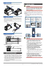
1.3 Wall Mounting
Mount the converter onto the FRK panel as shown below or
mount it directly on the wall.
FRK panel
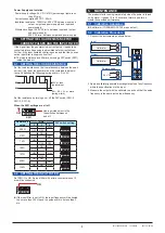
1.4 DIN Rail Mounting
Place the converter so that the DIN rail fits into the upper part of
the DIN-rail groove at the rear of the converter, and push until it
clicks. The converter is fixed by a slide lock (at the lower part on
the rear side of the converter).
To remove the converter, pull down the slide lock using a slotted
screw-driver.
Slide lock
DIN rail
DIN rail groove
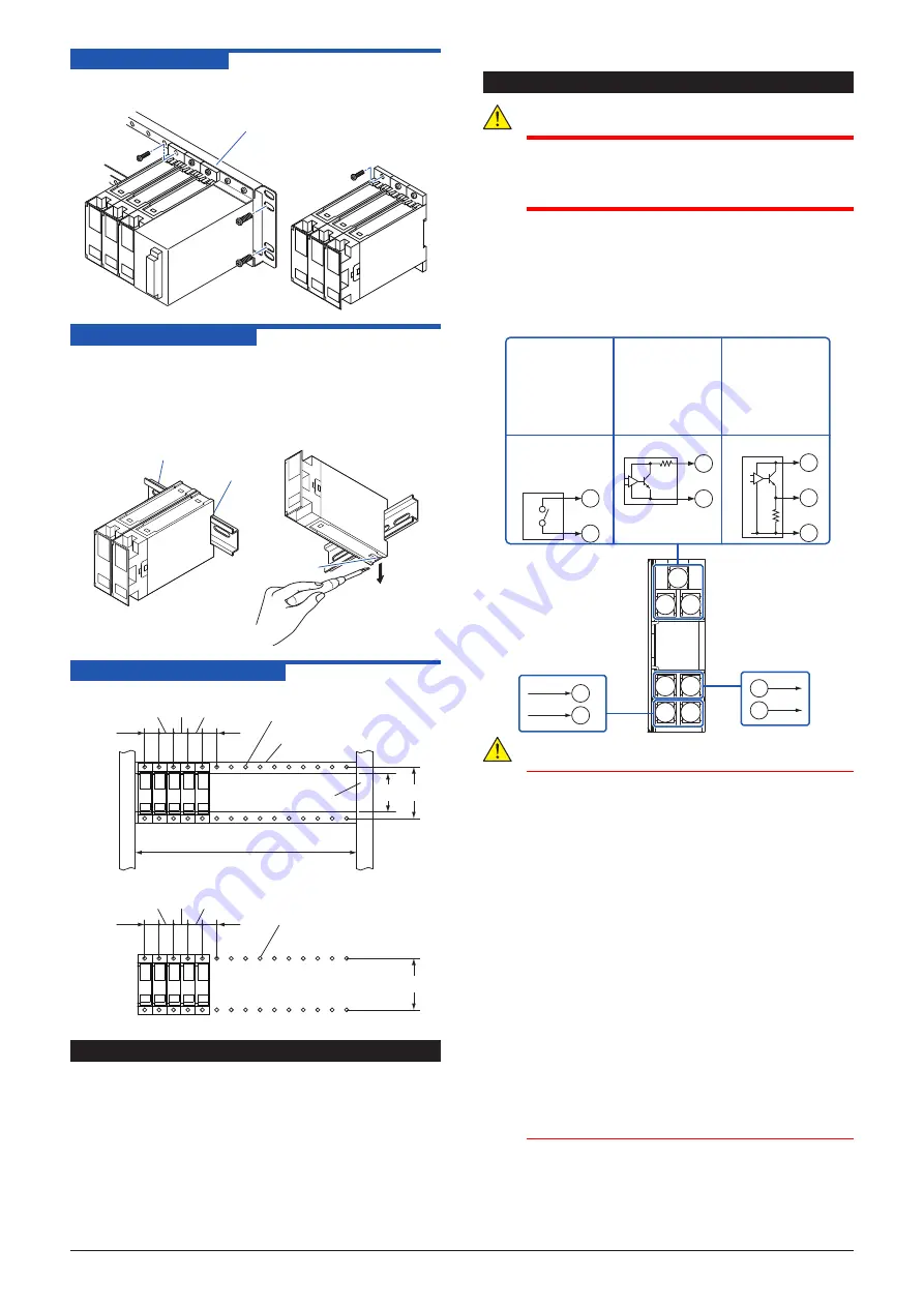
1.5
Mounting Dimensions
Angle Mounting Dimensions
Mounting angle
M4×0.7 Mounting screw
Support
24.5
24.5
24.5 24.5 24.5
n×24.5+2
Unit: mm
73 90
Wall Mounting Dimensions
M4×0.7 Mounting screw
Unit: mm
24.5
24.5
24.5
24.5 24.5
90
2. INSTALLATION LOCATION
z
Avoid the following environments for installation locations:
Areas with vibration, corrosive gases, dust, water, oil, solvents,
direct sunlight, radiation, a strong electric field, and/or a strong
magnetic field, altitude of more than 2000m above sea level.
z
If there is any risk of a surge being induced into the power line
and/or signal lines due to lightning or other factors, a dedicated
lightning arrester should be used as protection for both this
converter and a field-installed device.
z
Operating temperature/humidity range: 0 to 50ºC/5 to 90%RH
(no condensation)
3. EXTERNAL WIRING
WARNING
Be sure to turn OFF the power supply before wiring to
avoid the risk of electric shock. Use a tester or similar
device to ensure that no power is being supplied to a
cable to be connected
.
M4 screw terminals are provided for the connection of external
signals. Attach a crimp-on lug to each wire for connection to the
terminals.
z
Recommended cables: A nominal cross-sectional area of 0.5
mm
2
or thicker for signal cables, and that of 1.25 mm
2
or thicker
for power cables.
1
2
3
4
5
6
7
6
7
4
5
Output
Input
Power supply
1
2
3
1
2
2
3
Transmitter
Transmitter
Transmitter
PS+
+
–
+
–
+
–
PS+
–
+
–
When receiving
current pulse by
running a
transmitter on an
internal power
supply
When receiving
voltage pulse by
running a
transmitter on an
internal power
supply
When receiving
non-voltage
contact signal or
voltage pulse
CAUTION
● This instrument may output a pulse when the power
is turned on/off. Depending on the connected
devices, this pulse output is counted as “one
pulse.”
● Do not connect anything to the terminals that are
not used in the wiring diagram. Otherwise it may
cause the malfunction or damage.
● The power line and input/output signal lines should
be installed away from noise-generating sources.
Otherwise accuracy cannot be guaranteed.
● Adhere strictly to the specifications to avoid
overheating or damage. Before turning on the
power, ensure the following:
(a) Power supply voltage and input signal value applied
to the product should meet the required specifica
-
tions.
(b) The external wiring to the terminals are as specifica
-
tions.
● Do not operate the product in the presence of
flammable or explosive gases or vapors.
● The product is sensitive to static electricity;
exercise care in handling. Before you operate the
product, touch a nearby metal part to discharge
static electricity.
Содержание JUXTA F Series
Страница 4: ...Blank Page ...