


35
7.1.3 Our portable end milling machine KM 213-215 is used for working of non-ferrous materials, aluminum and PVC
mullion profiles to make <T > connections.
7.1.4 Control whether cutting tools (FIGURE 10 NO: 47) are inserted safely to their places.
7.1.5 Control cutting tools against corrosion, distortion and fractions. If cutting tools are damaged, change them.
7.1.6 Cutting tool must process on the part after machine is operated and cycled.
7.1.7
Do not process the profile before clamping the work piece properly.
7.2 Operation
7.2.1 Switch the system start switch to “1” (FIGURE 11 – NO.49)
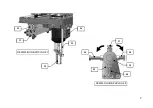
7.2.2 Place mullion profile on the machine table and push it forward until it contacts the stopper (FIGURE 8, NO.36).
NOTE: Lengths of profile leaning screws can be adjusted by loosening the nuts. This product has 4 pieces of
leaning screws. The mechanism holding screws is turnable. (FIGURE 8) By rotating the mechanism
desired leaning screw can be adjusted.
7.2.3 By pushing the clamp button (FIGURE 11 NO: 53), with the help of two clamps on the machine (FIGURE 3 NO:
12 / 17) fix the profile which was touched to the edge of the support
7.2.4 This machine has angled milling process. For this process loosen the M12 nut (FIGURE 3 NO.8) and screw
(FIGURE 5 NO.23) on the set square (FIGURE 5.NO.22). With the aid of angle label (FIGURE 5 NO.24) move
the set square to desired angle and re-tighten M12 nut. Apply the above mentioned operation order.
7.2.5 Press the Motor Start button (FIGURE 11 NO.51) to rotate the milling cutters.Press the Cutting Start button
(FIGURE 11 NO.52) to start the travel of the milling cutter group. The milling cutters carry out the milling
operation and return to the original position automatically. Press the Motor Stop button (FIGURE 11 NO.51) to
finish the operation.