background image

12

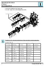
3.5- D...0S... Types For 2 and 3 Staged Gear Units

Standard D...0S... type basic part diagram. Parts may differ for special applications.

Standard Part List

31

25

12

4

4

4

1

3

4

6

30

32

33

34

35

36

19

20

21

22

23

24

26

27

2829

7

8

9

10

11

13

14

15

16

17

18

5

2

Only Valid For 3 Stages

1- Pin Screw

9-  Spacer

17- Circlip

25- Key

33- Shaft Gear

2- Shrink Disk 10- Bearing

18- Oil Seal

26- Gear

34- Bearing

3- Housing

11- Output shaft

19- Closing Cap 27- Spacer

35- Circlip

4- Plug

12- Key

20- Circlip

28- Bearing

36- Closing Cap

5- Cover Plate 13- Gear

21- Spacer

29- Spacer

6- Bolt

14- Spacer

22- Spacer

30- Bearing

7- Oil Seal

15- Bearing

23- Bearing

31- Gear

8- Circlip

16- Spacer

24- Shaft Gear

32- Key

Operating Instructions

D Series

YILMAZ REDÜKTÖR

Part Designations

Содержание D Series

Страница 1: ...YILMAZ REDÜKTÖR ISO 9001 YILMAZ REDÜKTÖR ISO 9001 D Series Gear Units Operating Instructions OIDEX0104 1114 o ...

Страница 2: ......

Страница 3: ...ameplate of the Gear Unit 20 5 3 Check the Ambient Conditions and Temperature 20 5 4 Check Fitting Elements and the Shaft Dimensions to Fit 20 5 5 Check the Voltage Supply 22 5 6 Check the Mounting Position 22 5 7 Usage of Breather Plug 22 5 8 Check the oil level 23 5 9 Check shaft ends and mounting faces 23 5 10 Cover abrasive ambient 23 5 11 Check accessibility to filling breather and drain plug...

Страница 4: ...R Contents 7 Maintenance Inspection 36 8 Lubrication 37 8 1 Oil types 37 8 2 Changing the oil 37 8 3 Mounting Positions 38 8 4 Oil Quantities 39 41 9 Troubleshooting Guide 43 10 Appendix 48 Warranty conditions 48 Warranty 49 Service Contact Points 50 ...

Страница 5: ...ar units and is applicable only for these series If any different type of gear unit is used please ask YILMAZ REDUKTOR For special application and modified gear units ask YILMAZ REDUKTOR for validity The D series gear units are with input shaft and without motor The electric motor which will be con nected to the gear unit must also be in conformity with the ATEX 94 9 EC standards All the external ...

Страница 6: ...ed and Hollow Shaft output 0S Shrink Disk Output 0E Extruder Output D R 4 7 4 02 90S 4 L05 Stage 2 Stages 3 Stages 4 Stages 5 Stages 6 Stages Brake L 220 V With Fan P 24 V With Fan S 220 V Without Fan Z 24 V Without Fan 01 10 Nm 02 25 Nm 04 40 Nm 05 50 Nm 10 100 Nm 20 200 Nm 30 300 Nm 40 400 Nm For DN Types A06 63 B5 A09 90 B5 A13 132 B5 A25 250 B5 B06 63 B14 B09 90 B14 B13 132 B14 A28 280 B5 A07 ...

Страница 7: ...0 M1 Abbreviations Type Type of gearbox S N Serial Number of gear unit Production Date can be learnt from YILMAZ with this number IP Enclosure P Max Allowed Power M Output torque n Input speed n Output speed FR Max allowed radial load at output shaft FR Max allowed radial load at input shaft FA Max allowed axial load at output shaft FA Max allowed axial load at input shaft Oil Filled oil inside th...

Страница 8: ...ar 20 Spacer 28 Spacer 5 Screw 13 Spacer 21 Spacer 29 Bearing 6 Oil Seal 14 Bearing 22 Bearing 30 Gear 7 Circlip 15 Spacer 23 Shaft Gear 31 Key 8 Spacer 16 Circlip 24 Key 32 Gear Standard D 00 type basic part diagram Parts may differ for special applications Standard Part List 30 24 11 3 3 3 1 2 3 5 29 31 32 33 34 35 18 19 20 21 22 23 25 26 27 28 6 7 8 9 10 12 13 14 15 16 17 4 Only Valid For 3 Sta...

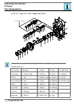
Страница 9: ...ing Cap 5 Bolt 13 Gear 21 Spacer 29 Spacer 6 Oil Seal 14 Spacer 22 Spacer 30 Bearing 7 Circlip 15 Bearing 23 Bearing 31 Gear 8 Bearing 16 Spacer 24 Shaft Gear 32 Key Standard D 01 type basic part diagram Parts may differ for special applications Standard Part List 31 25 11 3 3 3 1 2 3 5 30 32 33 34 35 36 19 20 21 22 23 24 26 27 28 29 6 7 8 9 10 13 14 15 16 17 18 4 12 Only Valid For 3 Stages Operat...

Страница 10: ...21 Closing Cap 30 Bearing 4 Cover Plate 13 Gear 22 Circlip 31 Spacer 5 Bolt 14 Spacer 23 Spacer 32 Bearing 6 Oil Seal 15 Bearing 24 Spacer 33 Gear 7 Circlip 16 Spacer 25 Bearing 34 Key 8 Spacer 17 Circlip 26 Shaft Gear 35 Shaft Gear 9 Bearing 18 Seal 27 Key 36 Bearing 33 27 11 3 3 3 1 2 3 5 32 34 35 36 37 38 21 22 23 24 25 26 28 29 30 31 6 7 8 9 10 13 14 15 16 17 18 4 12 19 20 Only Valid For 3 Sta...

Страница 11: ...t 13 Spacer 21 Circlip 29 Bearing 37 Closing Cap 6 Oil Seal 14 Bearing 22 Spacer 30 Spacer 7 Circlip 15 Spacer 23 Spacer 31 Bearing 8 Spacer 16 Circlip 24 Bearing 32 Gear Standard D 03 type basic part diagram Parts may differ for special applications Standard Part List 32 26 11 3 3 3 1 2 3 5 31 33 34 35 36 37 20 21 22 23 24 25 27 28 29 30 6 7 8 9 10 12 13 14 15 16 17 4 18 19 Only Valid For 3 Stage...

Страница 12: ... For 3 Stages 1 Pin Screw 9 Spacer 17 Circlip 25 Key 33 Shaft Gear 2 Shrink Disk 10 Bearing 18 Oil Seal 26 Gear 34 Bearing 3 Housing 11 Output shaft 19 Closing Cap 27 Spacer 35 Circlip 4 Plug 12 Key 20 Circlip 28 Bearing 36 Closing Cap 5 Cover Plate 13 Gear 21 Spacer 29 Spacer 6 Bolt 14 Spacer 22 Spacer 30 Bearing 7 Oil Seal 15 Bearing 23 Bearing 31 Gear 8 Circlip 16 Spacer 24 Shaft Gear 32 Key Op...

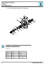
Страница 13: ...acer 6 Bolt 10 Hollow Shaft Output 3 Flange 7 Seal 11 Spacer 4 Bolt 8 Bearing 12 Seal Standard D 0E type basic part diagram Parts may differ for special applications Standard Part List 1 2 3 4 5 6 7 8 9 9 10 11 12 Operating Instructions D Series YILMAZ REDÜKTÖR Part Designations ...

Страница 14: ... Parts may differ for special applications Parts List 1 Circlips 6 Circlips 11 Key 2 Bearing 7 Shaft 12 Key 3 Gear 8 Seal 13 Bolt 4 Oil plug 9 Gear 14 Additional Housing 5 Bearing 10 Circlips 15 Screw Pin 1 2 3 4 5 6 7 8 9 10 11 12 13 14 15 4 Operating Instructions D Series YILMAZ REDÜKTÖR Part Designations ...

Страница 15: ... Bearing 28 Gear 36 Oil plug 5 Spacer 13 Output Flange 21 Spacer 29 Key 37 Top side cover 6 Gear 14 Bolt 22 Gear 30 Gear 38 Screw Pin 7 Bearing 15 Key 23 Bearing 31 Bearing 8 Key 16 Output Shaft 24 Circlips 32 Circlips 1 2 3 4 5 6 7 9 11 8 12 16 18 19 20 21 22 23 24 15 17 25 10 26 27 28 30 31 32 29 34 35 36 37 38 33 14 13 N Type 2 and 3 stages are additional housing of D series 5 stages and 6 stag...

Страница 16: ...es Motor Flange for Direct Coupled Types 1 2 3 4 5 6 7 8 10 9 Parts List 3 10 DN DV Types B5 B14 Motor Flange 1 2 3 4 5 6 7 8 10 9 1 Shaft 6 Seal 2 Circlips 7 Gear 3 Bearing 8 Circlips 4 Circlips 9 Nut 5 B5 B14 Flange 10 Key Parts List Operating Instructions D Series YILMAZ REDÜKTÖR Part Designations ...

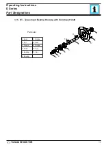
Страница 17: ...ing Housing with Solid Input Shaft 1 Seal 7 Circlips 2 Nut 8 Gear 3 Flange 9 Circlips 4 Shaft 10 Key 5 Bearing 11 Key 6 Bearing Parts List 1 2 3 4 5 6 7 8 9 11 10 Operating Instructions D Series YILMAZ REDÜKTÖR Part Designations ...

Страница 18: ...he requirements of the directive 94 9 EC The gearbox is started up maintained and operated according this manual The gearbox is incorporated with 94 9 EC confirming parts machines A motor connected to the gear unit is only allowed to be operated in the frequency entries so that the data provided on nameplate of the gear unit is not exceeded and is accord ance with the nameplate The input speed ran...

Страница 19: ...wrap and pack it in con tainer A moisture indicator should be placed around the container to observe the mois ture Relative atmospheric humidity should not exceed 50 The container should be kept under roof which protects from snow and rain Under this condition the gear unit can be stored up to 3 years with regular check Without Packing Use protection oil for the output shaft and connection surface...

Страница 20: ... oils acids gases vapors or radiated interference are present when the gear unit is being installed The ambient temperature must be in accordance with the oil tables given on the manual If it is different contact YILMAZ REDUKTOR for special solutions The ambient air temperature must not exceed 40 degrees celcius as mentioned on the nameplate The cooling air surrounding the gear unit must below 40 ...

Страница 21: ... Shaft Tolerance H8 Output Shaft Diameter Output Shaft Tolerance DIN748 Up to 50mm k6 Over 50mm m6 Flange Centering Shoulder Diameter Centering Shoulder Tolerance g6 D 172 173 30 0 02 0 30 0 02 0 80 0 01 0 03 D 272 273 35 0 03 0 35 0 02 0 86 0 02 0 04 D 282 283 40 0 03 0 40 0 02 0 110 0 02 0 04 D 372 373 45 0 03 0 40 0 02 0 110 0 02 0 04 D 472 473 50 0 03 0 50 0 02 0 130 0 02 0 04 D 572 573 60 0 0...

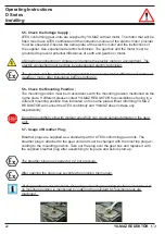
Страница 22: ...me plate If different please contact YILMAZ REDUKTOR for possibilities of using in a different mounting position then indicated on the name plate without informing YILMAZ REDUKTOR will cancel the ATEX conformity and YILMAZ does not take any responsibility Do not mix synthetic oils with mineral oils which can cause serious damage on the gear unit 5 7 Usage of Breather Plug Breather plugs are suppli...

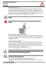
Страница 23: ...g available solvents on your market By using this do not touch sealing lips or painting of the housing 5 10 Cover abrasive ambient If the gear unit will be placed on a abrasive ambient be sure that the output seals are covered so that no abrasive material chemicals or water touches the seals Any pressure coming from outside over the seals can cause that the out staying sub stances to enter the gea...

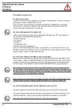
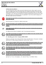
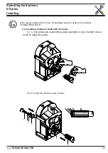
Страница 24: ...he following illustrations Only ATEX approved input and output elements are allowed to be used assuming the ele ments are subject to Directive 94 9 EC 6 1 Installing gear units in category II2G D II3G D Explosion proof gear units comply with the design requirements for unit group II catagory 2G 2D 3D 3G These units are intended for use in zones 1 and 21 The gear units in catagory II2D must be used...

Страница 25: ...t YILMAZ REDUKTOR o 6 2 2 Fasten the bold as shown below 6 2 Installing Customer Shaft with Shoulder 6 2 1 Use anti seize assembling paste available on your market Use a brush to apply the paste 1 2 4 5 6 3 6 5 4 3 2 1 Operating Instructions D Series YILMAZ REDÜKTÖR Installing ...

Страница 26: ...arts as shown 6 3 2 Use the disassemble set from YILMAZ and fasten the bold as shown bellow to take out the output shaft 4 3 2 1 5 6 6 4 3 2 1 5 1 3 5 6 2 4 1 Retaining Bolt 2 Circlip 3 Lock Washer 4 Washer 5 Hollow Shaft 6 Customer Shaft Operating Instructions D Series YILMAZ REDÜKTÖR Installing ...

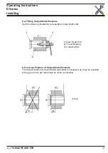
Страница 27: ...its 6 5 Correct Position of Output Shaft Elements The Output Shaft unit transmission elements must placed as close as possible to the gear unit to get radial load as close as possible 1 Gear Shaft End 2 Thrust Bearing 3 Coupling Hub 1 Hub Operating Instructions D Series YILMAZ REDÜKTÖR Installing ...

Страница 28: ...s some clearance between the two shafts 6 6 2 While fitting couplings be sure that there is no eccentricity between the two shafts 6 6 3 While fitting couplings be sure that the two shafts are not angular miss aligned Operating Instructions D Series YILMAZ REDÜKTÖR Installing ...

Страница 29: ...ing torques Type Bolt Tightining Torque Nm D 172 173 M10 20 D 272 273 M12 20 D 282 283 M16 40 D 372 373 M16 40 D 472 473 M16 40 D 572 573 M20 80 D 672 673 M20 80 D 772 773 M24 200 D 872 873 M24 200 D 972 973 M24 200 Operating Instructions D Series YILMAZ REDÜKTÖR Installing ...

Страница 30: ... the shaft and shrink disk hollow The surfaces must be free from oil or any dirt The solvent must be removed from the surfaces as well 6 8 Assembling customer shaft with shrink disk 6 8 1 Loosen the bolts of the shrink disk Operating Instructions D Series YILMAZ REDÜKTÖR Installing ...

Страница 31: ...isk shoulder and the hollow shaft shoulder of the gearbox 1 2 3 4 1 Customer Shaft 2 Bronze Ring 3 Hollow Shaft 4 Shrink Disk Type Bolt Tightening Torque Nm D 1 M8 30 D 2 M8 30 D 3 M8 30 D 4 M8 30 D 5 M10 59 D 6 M10 59 D 7 M12 100 D 8 M14 160 D 9 M14 160 Operating Instructions D Series YILMAZ REDÜKTÖR Installing ...

Страница 32: ...32 6 9 Disassembling customer shaft with shrink disk 6 9 1 Loosen the bolts of the shrink disk and take out the shaft Operating Instructions D Series YILMAZ REDÜKTÖR Installing ...

Страница 33: ...33 6 10 Assembling Gear Unit with Torque Arm 6 10 1 Use the torque arm connection according the following drawing Operating Instructions D Series YILMAZ REDÜKTÖR Installing ...

Страница 34: ...34 6 10 2 Assemble the parts as shown bellow 1 2 3 4 4 5 6 7 1 Bolt 4 Rubber Buffer 7 Bolt 2 Washer 5 Bolt 3 Washer Ring 6 Fixing Plate Operating Instructions D Series YILMAZ REDÜKTÖR Installing ...

Страница 35: ...s Type d b b1 h D 17 17 54 27 158 D 27 17 54 27 170 D 28 17 54 27 198 D 37 17 56 28 218 D 47 22 80 40 278 D 57 22 86 43 346 D 67 26 110 55 395 D 77 26 116 58 485 D 87 32 160 80 550 D 97 32 165 82 5 660 h1 b1 b h Ød Operating Instructions D Series YILMAZ REDÜKTÖR Installing ...

Страница 36: ...hours or every 6 months Every 4 000 working hours Every 10 000 working hours or every 3 years Every 25 000 working hours Check for oil leakage x Check for oil level x Check oil leakage from seal x Check Rubber buffer x Change if necessary Check Bearings Noise x Change if necessary Change Mineral Oil x See Below for details Change Synthetic PAO Oil x See Below for details Change Sealing x Change Be...

Страница 37: ...F H1 15 25 320 Optileb GT 320 Klüberoil 4 UH1 320 N Mobil SHC Cibus 320 Cassida Fluid GL 320 Nevastane SL 320 Biodegradable Oil CLP E 25 40 320 Tribol BioTop 1418 320 Klübersynth GEM 2 320 Carter Bio 320 Mineral Grease 20 120 Working Temperature ºC Aralub HL3 Energrease LS 3 Spheerol AP3 Centoplex 2 EP Mobilux EP 3 Alvania RL3 Multis Complex EP 2 Synthetic Grease 30 100 Working Temperature ºC Ener...

Страница 38: ... Mounting Positions Figured mounting positions of M1 to M6 are de termined as reference of directional position of the gearbox Mounting surfaces are not binding Figured mounting positions of M1 to M6 are determined as reference of directional position of the gearbox Mount ing surfaces are not binding M2 ...

Страница 39: ...3 9 DR373 3 2 3 7 2 0 3 5 3 3 3 5 DR472 6 8 7 0 4 6 6 0 6 0 6 2 DR473 6 4 8 4 5 5 5 0 7 2 7 3 DR572 11 4 12 7 8 6 11 4 10 0 11 0 DR573 11 2 12 4 7 4 9 6 11 5 11 35 DR672 19 0 20 0 15 1 16 0 19 5 19 5 DR673 18 0 18 0 14 0 15 0 15 0 16 DR772 29 0 30 0 22 0 24 0 25 0 27 0 DR773 27 2 28 0 20 0 22 5 22 0 24 0 DR872 46 0 48 0 39 0 38 0 42 0 44 0 DR873 43 0 45 0 32 0 36 0 40 0 42 0 DR972 78 0 81 0 59 0 6...

Страница 40: ... 1 5 7 4 1 5 9 6 1 5 11 5 1 5 11 5 1 5 DR674 18 0 4 0 18 0 4 0 14 0 4 0 15 0 4 0 16 5 4 0 17 0 4 0 DR774 27 2 4 0 28 0 4 0 20 0 4 0 22 5 4 0 27 0 4 0 27 0 4 0 DR874 43 0 6 0 45 0 6 0 32 0 6 0 36 0 6 0 43 0 6 0 43 0 6 0 DR974 73 0 4 0 76 5 4 0 54 0 4 0 61 0 4 0 73 0 4 0 73 0 4 0 Oil Quantities lt Symbols Drain plug Oil level Oil Filling and Vent plug A A A A A B B B B B Operating Instructions D Ser...

Страница 41: ... 12 4 2 1 7 4 2 9 6 2 1 11 35 1 4 11 5 1 4 DR576 11 2 1 1 12 4 2 7 4 1 9 9 6 2 11 35 1 3 11 5 1 3 DR675 18 0 1 2 18 0 2 1 14 0 2 15 0 2 1 16 1 4 15 0 1 4 DR676 18 0 1 1 18 0 2 14 0 1 9 15 0 2 16 1 3 15 0 1 3 DR775 27 2 2 28 0 3 4 20 0 3 1 22 5 3 4 24 0 2 8 22 0 2 8 DR776 27 2 1 9 28 0 3 3 20 0 3 22 5 3 3 24 0 2 6 22 0 2 6 DR875 43 0 2 45 0 3 4 32 0 3 1 36 0 3 4 42 0 2 8 40 0 2 8 DR876 43 0 1 9 45 ...

Страница 42: ...42 Appendix Operating Instructions D Series YILMAZ REDÜKTÖR Cooling Options ...

Страница 43: ...e motor with direct voltage according to its name plate and still same problem the load may be too high for the chosen motor Go to ID 003 9 Troubleshooting Guide All the operations below must be done by authorized and skilled mechanician electrician Inform YILMAZ REDUKTOR before making any change to the gearbox Only oil change is allowed to change without information Do not make anything if you ar...

Страница 44: ...irming check the oil type and oil quantity level according your mounting position and check the nameplate mounting position If nameplate mounting position does not fit the actual position go to ID 100 009 Gearbox is Heating Up too Much You are using Helical Gear Box Ambient temp is lower than 40 Cel sius Measure the surface temp using a temperature measuring device under full load If the temp is u...

Страница 45: ... tion The plug may be not tight enough There are some parti cles under the plug rubber surface Clean and tighten the plug If still same problem go to ID 100 019 Oil is Leaking Oil Leakage from Housing Observe exactly where the oil is coming out It could be seal or plug point where it comes out and leaks over the housing If this is your case go to ID 018 019 If you are sure oil comes out from housi...

Страница 46: ... Check if you are using the correct diameter of chain drive and you are not exceeding max allowed ra dial load Check the position of your output element and re calculate your radial load and check if this fit to the maximum allowed radial load Go to ID 100 027 Gearbox is stopping too late You are using braked motor Please check the wiring diagram of the brake There are two different kind of brake ...

Страница 47: ......

Страница 48: ...the date which the company or representative was made aware of the problem and ends on the date of the re start up 4 If the product fails to operate because of a manufacturing or assembly failure during the warranty time the product will be repaired free of charge 5 If the product fails to operate because of a manufacturing or assembly failure during the warranty time and it is not possible to rep...

Страница 49: ...The time for repair service will be added to the warranty time For detailed warranty conditions please refer the back side of this page Serial No Type Manufacturer Company YILMAZ REDUKTOR Sanayi ve Ticaret A S Address ATATÜRK Mah Lozan Cad No 17 P K 34522 Esenyurt Istanbul TURKIYE Telephone 90 0 212 886 90 01 8 line Fax 90 0 212 886 54 57 Stamp and Signature Supplier End User With signing this par...

Страница 50: ...06 03 90 0 212 567 40 78 90 0 212 567 04 11 90 0 212 567 45 07 90 0 212 567 00 70 Fax 90 0 212 567 99 75 e mail yilmaz yr com tr web www yr com tr Factory Tel 90 0 212 886 90 01 8 line 90 0 212 886 50 43 90 0 212 886 50 44 90 0 212 886 52 82 Fax 90 0 212 886 54 57 e mail yilmaz yr com tr web www yr com tr Outside Turkey Please contact the main service point mentioned above You will be directed to ...

Отзывы: