7
○
1 On/Off Switch
Main power switch of slit lamp.
2 Accessories Drawer
Страница 1: ...YF 100 Slit Lamp User Manual Version 1 4 Revision Date 2023 01...
Страница 2: ...om en Manual de usuario Enlace de descarga www yeasn com en Kullan m K lavuzu ndirme linki www yeasn com en Manuale d uso Link per il download www yeasn com en Link zum Herunterladen des Benutzerhandb...
Страница 3: ...tion in promotional materials and packing boxes is subject to changes due to performance improvement without additional notice Chongqing Yeasn Science Technology Co Ltd reserves the rights to update t...
Страница 4: ...stall base unit D 13 4 3 3 Install Rail cover E 14 4 3 4 Install Slit projector unit B 14 4 3 5 Install Eyepiece unit A 15 4 3 6 Install Breath screen F 15 4 3 7 Connect the plug 16 4 4 Checking after...
Страница 5: ...6 2 Maintenance and care 22 7 Cleaning and protection 22 8 Environmental Conditions and Service Life 22 9 Troubleshooting guide 23 10 Circuit diagram 24 11 Manufacturer s Responsibility 24 12 Disposa...
Страница 6: ...lar converging 2 Model of magnifying 5 steps by drum rotation 3 Eyepieces 12 5 4 Total magnification rate 6 4 10 16 25 40 5 Range of PD adjustment 55mm to 80mm 6 Diopter adjustment 5 00D to 5 00D 1 3...
Страница 7: ...anufacturer ate of manu erial numbe ountry of m t n ptor 1 1 i imension n 6 1 1 ecifications nd indicat ations are pa ate is not p stributors r ufacture er manufacture 70mm Red L 100 240 V A 12 V DC 3...
Страница 8: ...sult instructions for use Refer to instruction manual booklet Authorized European representative Catalogue number Unique Device Identifier Model number G W Gross Weight DIM Dimension Attention Please...
Страница 9: ...any kind of liquid drop on the instrument To avoid place in humid dusty or rapid humidity and temperature variation ambient conditions Dedicated power adaptor configured for the device should be used...
Страница 10: ...reduce the device s resistance to interference Do not use a power adaptor that is not configured with the device otherwise it may increase the electromagnetic emission amount which may reduce the capa...
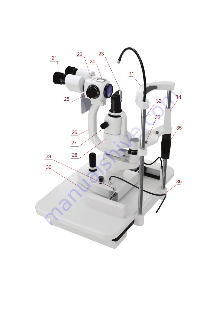
Страница 11: ...6 3 Instrument structure...
Страница 12: ...7 1 On Off Switch Main power switch of slit lamp 2 Accessories Drawer...
Страница 13: ...llumination 7 Filter Base Changing filters by turning the base and meet requirement of various inspections 8 Slit Apertures Adjustment Base Changing the Slit Apertures by turning the base 9 Breath Scr...
Страница 14: ...ovement of microscope arm and make it not able to turn in order to make the positioning of observation easily 19 Rail Cover To protects the rail surface 20 Power socket Supply power to slit lamp throu...
Страница 15: ...n the slide plate 31 Head Rest Support the fore head of the testee position the head of the testee 32 Eye Position Mark When the horizontal center of testee eye in the same horizontal plane of this ma...
Страница 16: ...11 4 Installing This instruction manual is for YF 100 Slit Lamp All parts must be taken out carefully from the package and then be put on installing...
Страница 17: ...ch 1 The three units are already installed well into a component R Power box 1 S Accessories box 1 H Power adaptor 1 4 2 Accessories list No Parts name Qty Note J Dust plate 1 L Focusing test rod 1 M...
Страница 18: ...to tighten the two hexagon socket screws U Figure 1 4 3 2 Install base unit D 1 Install the gear wheels of both sides of Base unit D on the gears of workbench G 2 Note that the gear wheel should be i...
Страница 19: ...e out the hexagon socket countersunk head screws Figure 4 beneath the central shaft of Slit projector unit B with the allen key O Figure 4 2 Connect the central shaft of Slit projector unit B to conne...
Страница 20: ...nto the U guide which supports the bent arm Tighten the connector locking knob P after the front part of U groove getting close to the connector locking knob Figure 6 Note please do not touch the opti...
Страница 21: ...the power box R 4 4 Checking after installing 4 4 1 Power connection The power adaptor we use is double pin plug please check matching Note please use the specialized power cord equipped with the ins...
Страница 22: ...trol knob and switch the brightness of slit image on flat surface of the Focusing test rod to the middle grade 3 Turn the slit adjustment knob and switch the slit image on the flat surface of the Focu...
Страница 23: ...value to zero and then you can see the Focusing test rod is clear 5 1 2 PD adjustment Figure 10 1 Hold the left and right prism base cover observe he slit image on flat surface of the Focusing test ro...
Страница 24: ...sk the testee to stare at the lamp with the spare eye to fix the sight line of the testee 2 Fixation lamp can be turned freely to adjust the sight line of the testee 5 3 Three dimensional location of...
Страница 25: ...he width is14mm the slit image is round 2 Change aperture rotate the aperture base you can get four different types of round light spot with diameters being 0 3mm 5 5mm 9mm 14mm and one gear which can...
Страница 26: ...rizontal and vertical direction and the angle can be read on the scale Figure 14 Figure 14 5 Insert dispersion lens when there is need to disperse the illumination light rotate the dispersion lens int...
Страница 27: ...repairs may only be performed by trained specialists 7 Cleaning and protection 1 Cleaning of optical parts if dusts or dirt stay on the lens or mirror you can wipe them out lightly with cotton dipped...
Страница 28: ...list below for guidance If the trouble is still not solved please contact Yeasn or its authorized distributor for repair services Trouble Possible cause Solution Illumination lamp failure The power p...
Страница 29: ...the room are in conformity with relevant requirements and The device is used according to the User Manual 12 Disposal and Environmental protection INFORMATION FOR USERS This product bears the selectiv...
Страница 30: ...proper performance and operation 4 Caution this machine should not be used adjacent to or stacked with other equipment and that if adjacent or stacked use is necessary this machine should be observed...
Страница 31: ...arth 1 kV differential mode 2 kV common mode Mains power quality should be that of a typical commercial or hospital environment Voltage dips short interruptions and voltage variations on power supply...
Страница 32: ...mpliance level in each frequency range b Interference may occur in the vicinity of equipment marked with the following symbol Radiated RF IEC 61000 4 3 3 V m 80 MHz to 2 5 GHz 3 V m NOTE1 At 80 MHz an...
Страница 33: ...eparation distance according to frequency of transmitter m 150 KHz to 80 MHz 80 MHz to 800 MHz 800 MHz to 2 5 GHz 0 01 0 12 0 12 0 23 0 1 0 38 0 38 0 73 1 1 2 1 2 2 3 10 3 8 3 8 7 3 100 12 12 23 For t...