


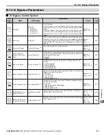


B.15 Defaults by Drive Model
The following tables show parameters and default settings that change with the drive model selection (o2-04).
Table B.4 208 V Default Settings by Model Selection
No.
Name
Unit
Default Settings
–
Bypass Model Z1B1
–
D002
D003
D004
D007
D010
D016
D024
D031
D046
D059
D075
o2-04
Drive Model Selection
Hex.
66
68
6A
6B
6D
6E
6F
b3-04
V/f Gain during Speed Search
%
100
100
100
100
100
100
100
b3-06
Output Current 1 during Speed Search
–
0.5
0.5
0.5
0.5
0.5
0.5
0.5
b3-08
Current Control Gain during Speed Search
(Speed Estimation Type)
–
0.50
0.50
0.50
0.50
0.50
0.50
0.50
b3-11
Speed Search Method Switching Level (Speed
Estimation Type)
–
5.0
5.0
5.0
5.0
5.0
5.0
5.0
C6-02
Carrier Frequency Selection
–
2
2
2
2
2
2
2
E2-01
Motor Rated Current
A
10.60
16.70
24.20
30.80
46.2
59.4
74.8
E2-03
Motor No-Load Current
A
3.00
4.50
5.10
8.00
11.2
15.2
15.7
L2-03
Momentary Power Loss Minimum Baseblock
Time
s
0.5
0.6
0.7
0.8
0.9
1
1
L2-05
Undervoltage Detection Level (Uv1)
–
190
190
190
190
190
190
190
L8-02
Overheat Alarm Level
°C
80
80
105
105
110
110
115
L8-06
Input Phase Detection Level
–
16.0
21.0
15.0
18.0
22.0
23.0
24.0
L8-09
Output Ground Fault Detection Selection
–
0
0
0
0
0
0
1
L8-38
Carrier Frequency Reduction
–
2
2
2
2
2
2
2
No.
Name
Unit
Default Settings
–
Bypass Model Z1B1
–
D088
D114
D143
D169
D211
D273
o2-04
Drive Model Selection
Hex.
70
72
73
74
75
76
b3-04
V/f Gain during Speed Search
%
100
80
80
80
80
80
b3-06
Output Current 1 during Speed Search
–
0.5
0.5
0.5
0.5
0.5
0.7
b3-08
Current Control Gain during Speed Search (Speed
Estimation Type)
–
0.50
0.50
0.50
0.50
0.50
0.50
b3-11
Speed Search Method Switching Level (Speed
Estimation Type)
–
5.0
5.0
5.0
5.0
5.0
5.0
C6-02
Carrier Frequency Selection
–
2
2
2
2
2
2
E2-01
Motor Rated Current
A
88
114
143
169
211
273
E2-03
Motor No-Load Current
A
18.5
21.9
38.2
44.0
45.6
72.0
L2-03
Momentary Power Loss Minimum Baseblock Time
s
1
1.1
1.1
1.2
1.3
1.5
L2-05
Undervoltage Detection Level (Uv1)
–
190
190
190
190
190
190
L8-02
Overheat Alarm Level
°C
115
115
109
109
109
109
L8-06
Input Phase Detection Level
–
24.0
25.0
28.0
26.0
28.0
28.0
L8-09
Output Ground Fault Detection Selection
–
1
1
1
1
1
1
L8-38
Carrier Frequency Reduction
–
2
2
2
2
2
2
B.15 Defaults by Drive Model
356
YASKAWA ELECTRIC SIEP YAIZ1B 01E YASKAWA AC Drive – Z1000 Bypass Technical Manual
Содержание Z1000 CIMR-ZU*A Series
Страница 54: ......
Страница 422: ...E 7 Fault Codes 422 YASKAWA ELECTRIC SIEP YAIZ1B 01E YASKAWA AC Drive Z1000 Bypass Technical Manual...
Страница 463: ...Index This Page Intentionally Blank YASKAWA ELECTRIC SIEP YAIZ1B 01E YASKAWA AC Drive Z1000 Bypass Technical Manual 463...
Страница 465: ......


