6.4 Fault Detection
YASKAWA ELECTRIC
SIEP C710636 02B YASKAWA U1000 Technical Manual
355
T
rou
bl
es
hoot
ing
6
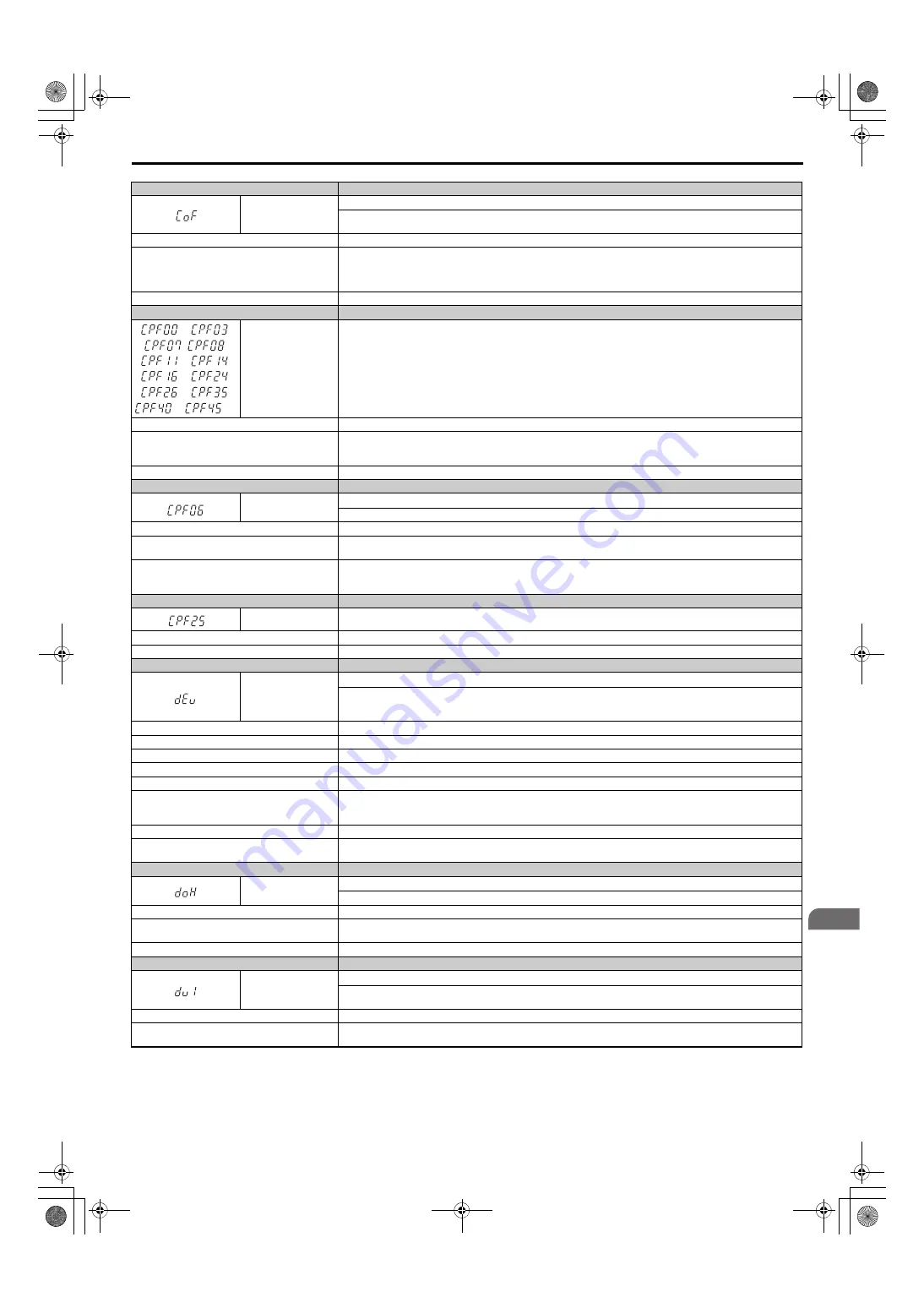
Digital Operator Display
Fault Name
CoF
Current Offset Fault
The current sensor is damaged or there was residual induction current in the motor (e.g., during sudden deceleration or when
coasting) when the drive attempted to start the motor.
Cause
Possible Solution
Due to residual induction current in the motor when the
drive attempted to start the motor, the drive attempted to
adjust the current offset value beyond the allowable
range.
• Create a motor restart sequence that allows enough time for the residual induction voltage to dissipate.
• Enable Speed Search at start (b3-01 = 1). Use the multi-function terminals to execute External Speed Search 1 and 2 (H1-
=
61 or 62).
Note:
When using a PM motor, both External Speed Search 1 and 2 perform the same operation.
Hardware is damaged.
Replace the drive.
Digital Operator Display
Fault Name
to
,
, ,
to
,
to
,
to
,
to
CPF00 to CPF03, CPF07,
CPF08, CPF11 to CPF14,
CPF16 to CPF24,
CPF26 to CPF35,
CPF40 to CPF45
Control Circuit Error
Cause
Possible Solution
Hardware is damaged.
• Cycle power to the drive.
• If the problem continues, replace either the control board or the entire drive. For instructions on replacing the control board,
contact Yaskawa or your nearest sales representative.
Connector on the operator is damaged.
Replace the operator.
Digital Operator Display
Fault Name
CPF06
Control Circuit Error
There is an error in the data saved to EEPROM.
Cause
Possible Solution
The power supply was switched off when parameters
were being saved to the drive.
Reinitialize the drive (A1-03 = 2220, 3330).
Hardware is damaged.
• Turn the power off and check the connection between the control board and the drive.
• If the problem continues, replace either the control board or the entire drive. For instructions on replacing the control board,
contact Yaskawa or your nearest sales representative.
Digital Operator Display
Fault Name
CPF25
Terminal Board not Connected
Cause
Possible Solution
Terminal board is not connected correctly.
Reconnect the terminal board to the connector on the drive, then cycle the power to the drive.
Digital Operator Display
Fault Name
dEv
Speed Deviation (for Control Mode with PG)
The deviation between the speed detection value for the pulse input and the speed reference after speed agreement was reached
exceeded the setting value of F1-10 for the time set in F1-11 or longer when the Operation Selection at Deviation was set to
continue operation (F1-04 = 3).
Cause
Possible Solution
Load is too heavy.
Reduce the load.
Acceleration and deceleration times are set too short.
Increase the acceleration and deceleration times (C1-01 through C1-08).
The load is locked up.
Check the machine.
Parameters are not set appropriately.
Check the settings of parameters F1-10 and F1-11.
Incorrect speed feedback scaling if terminal RP is used
as speed feedback input in V/f control.
• Set H6-02 to the same value as the speed feedback signal frequency when the motor runs at maximum speed.
• Adjust the speed feedback signal using parameters H6-03 through H6-05.
• Make sure the speed feedback signal frequency does not exceed the maximum input frequency of terminal RP.
Motor brake engaged.
Ensure the motor brake releases properly.
The torque limit is small for the load.
Increase the setting values of L7-01 to L7-04, the value of the torque limit from the analog input, or the value of the torque limit
set from the communication option.
Digital Operator Display
Fault Name
doH
Damping Resistor Overheat
The temperature of the built-in damping resistor exceeded the set value.
Cause
Possible Solution
• The capacity of the power supply is too small.
• The distortion in the power supply is too large.
• Increase the capacity of the power supply.
• Lower the impedance of the input power supply wiring.
A phase loss occurred in the input power supply.
Check the input power supply for phase loss or an imbalance in the interphase voltages.
Digital Operator Display
Fault Name
dv1
Z Pulse Fault
The motor turned one full rotation without the Z pulse being detected.
Note:
Available in CLV/PM control mode only.
Cause
Possible Solution
PG encoder is not connected, not wired properly, or is
damaged.
• Make sure the PG encoder is properly connected and all shielded lines are properly grounded.
• If the problem continues after cycling power, then replace either the PG option card or the PG encoder itself.
SIEP_C710636_02B_1_0.book 355 ページ 2015年11月25日 水曜日 午後4時56分


