background image


Page | 13  


NETWORK CONFIGURATION 

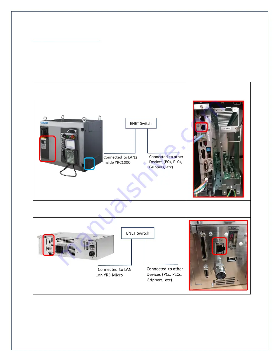
An Ethernet network will be used to establish communication between the SMART Series robot 
controller and the Robotiq 2F gripper.  Using the diagrams below, connect an Ethernet cable from the 
networking port of the robot controller (LAN2 on YRC1000, LAN on YRC1000micro) to an installed 
Ethernet switch.  

Network Layout (YRC1000) 

Controller Port       

(YRC1000) 


Network Layout (YRC1000micro) 

Controller Port        

(YRC1000micro) 


Exit ports for cable(s) 
network 

Содержание Smart Series

Страница 1: ...Robotiq 2 Finger Gripper Application Note for SMART Series Robots by Yaskawa Version 1 00 Andrew Boddiford 11 19 2018 ...

Страница 2: ...Page 2 DOCUMENT REVISION INFORMATION Date Version Number Document Changes 11 19 18 1 00 Initial version for SMART Series Robots by Yaskawa ...

Страница 3: ...tiq Universal Controller 11 Network Configuration 13 Change IP Address of Robotiq Gripper 15 Change IP Address of SMART Series Robot Controller 18 EtherNet IP Configuration on SMART Series Controller 20 External I O Allocation for Gripper 26 Load Robotiq Files Verify I O Allocation 32 Verify Gripper Communication and Operation 36 Define Physical Properties of Gripper on SMART Pendant 37 PROGRAMMIN...

Страница 4: ...sal Controller EtherNet IP Configuration 6 CBL COM 2065 10 HF Robotiq 10m High Flex Device Cable for Gripper 7 Robotiq 10ft Shielded USB Cable for Gripper Configuration 8 Robotiq Coupling Specific to Customer s SMART Series Robot 9 787 818 Wago 24VDC 3A DIN Rail Mount Power Supply 10 852 111 Wago DIN Rail Mount Industrial Ethernet Switch 11 Cat6 Ethernet Cables length determined by customer workce...

Страница 5: ...r Reference Only SUPPORTING DOCUMENTATION Item Part Version Name Description 1 Robotiq 2F 85_2F 140 Instruction Manual for e Series Grippers 2 RUC 140626 Robotiq Universal Controller Instruction Manual 3 184775 1 Yaskawa SMART Pendant Instructions Manual 4 184774 1 Yaskawa SMART Pendant INFORM Language Instructions Manual 5 Varies Yaskawa EtherNet IP Communication Function Instructions Manual 6 Va...

Страница 6: ... The diagram below illustrates the process required to integrate a Robotiq 2F gripper with a SMART Series Robot by Yaskawa The icons below each column represent the software platform required to complete each group of actions ...

Страница 7: ...1000 installed operational with EtherNet IP enabled 3 Connected Smart Pendant 4 Windows PC Win 7 8 9 or 10 5 Knowledge of basic robotic concepts 6 Familiarity with Yaskawa I O The Robotiq 2 Finger gripper can be customized for a specific application For example custom fingertip shapes materials can easily be attached and protective covers can be added to eliminate most pinch points Please see the ...

Страница 8: ...s of the available couplings and adapter plates please refer to the Spare Parts Kits and Accessories section Here are the steps to follow to mount the Gripper to your robot exploded view in the figure below 1 Screw the adapter plate or the coupling to the robot 2 Screw the coupling to the adapter plate if adapter plate is required 3 Screw the Gripper onto its coupling a Use caution not to damage t...

Страница 9: ...Page 9 SMART Series Robot Tool Flange Details ...

Страница 10: ...Robotiq 2F Gripper manual 2 With all devices powered OFF carefully route the gripper cable externally along the robot to connect the Robotiq gripper to its controller 3 Configure a common Ethernet network for your system a Connect the robot and gripper controllers to a common network b Set IP address of robot controller using Software Pendant if required c Set IP address of Robotiq gripper using R...

Страница 11: ...on 2 1 Safety Section 2 2 Intended Use Section 3 4 Power Supply Specifications Section 3 5 Wiring Wiring Instructions for Universal Controller Wire power from the 24 VDC supply to the Robotiq Universal Controller using a 3A inline fuse or fuse rated for the applicable gripper model Connect E Stop to Robotiq Universal Controller Connect the terminals on the gripper cable to the Robotiq Controller a...

Страница 12: ...ure to leave extra slack in the cable to allow for joint movement and rotation The full movement range of each axis should be tested before programming an application see the robot model s datasheet for maximum allowable travel for each axis The example below depicts HC10 with the Robotiq gripper cable routed externally to the arm ...

Страница 13: ...r and the Robotiq 2F gripper Using the diagrams below connect an Ethernet cable from the networking port of the robot controller LAN2 on YRC1000 LAN on YRC1000micro to an installed Ethernet switch Network Layout YRC1000 Controller Port YRC1000 Network Layout YRC1000micro Controller Port YRC1000micro Exit ports for cable s network ...

Страница 14: ...thernet switch LAN connection from SMART Series robot controller Ethernet switch Connection to workcell network for other devices USB port on Universal Controller e g used configure gripper IP address Network Design Decide how to structure the system network before changing the default IP addresses for the robot controller gripper controller and other external devices Has a network been establishe...

Страница 15: ...ange the gripper s IP address to one that is compatible with the desired network 1 Power ON the Universal Controller that is connected to the Robotiq 2F gripper 2 Connect a USB cable from Robotiq Universal Controller to the development PC 3 Open the Robotiq User Interface software installed on the development PC a Select 2 Finger a Press Auto Connect ...

Страница 16: ...ters change IP Address to the LAN2 network address reserved for the gripper on the YRC1000 controller 192 168 1 11 is factory default setting change the address to a different IP address that will be used for the LAN connection to the YRC1000 controller ...

Страница 17: ...ith Gripper for instructions to change LAN LAN2 address on the controller This example is 10 7 3 45 LAN2 match the address here with address for LAN2 in the YRC1000 controller 7 A confirmation dialog will appear on the Robotiq User Interface 8 The gripper s IP address is now set for communication with the robot controller ...

Страница 18: ...sing Yaskawa s Software Pendant For basic information on using Software Pendant see Chapter 12 of the Smart Pendant Instructions manual The steps to change the IP address of the robot controller are provided below 1 Connect to the robot controller using its current IP address with Software Pendant in Special Mode Maintenance Mode 2 Change Security Level to Management From the main menu navigate to...

Страница 19: ...the newly configured IP address 4 Press ENTER on the pendant to save the new setting s A Modify dialog should appear Optional To test the new address reboot the robot controller to exit Maintenance Mode Ping the controller from a development PC on the same network to verify that communication has been established Note EtherNet IP configuration requires Maintenance Mode the reboot can be delayed ...

Страница 20: ...tion for Scanner Before opening Software Pendant it is important to gather all the necessary information required to communicate with the gripper The table below shows the information needed to properly configure a Scanner This information and more is available in the Robotiq 2F gripper manual Name User Defined e g Robotiq 2F IP Address User Defined Input Size 24 byte 20 gripper 4 EIP header Outpu...

Страница 21: ...vices are present the list will be empty and press SELECT This will open a screen that has the basic configuration information for the device Chose and name for the gripper e g ROBOTIQ 2F Use Enter on the keypad and not Register to save the name ...

Страница 22: ... screen press Enter to save the new configuration A Modify dialog will appear YES takes the user to a newly populated Device Information List Next a Scanner for this device should be added and configured with the correct IP Address Select SYSTEM SETUP Option Function Next highlight EtherNet IP CPU Board DETAIL and press SELECT On the next screen highlight EtherNet IP CPU Board DETAIL and press SEL...

Страница 23: ...Page 23 On this screen first verify that the board is set to USED Contact Yaskawa if this is set to NOT USED Next highlight the Scanner DETAIL row and press SELECT ...

Страница 24: ...ess SELECT Press SELECT again to MODIFY this entry On the next screen highlight the desired device e g Robotiq 2F and press SELECT Robotiq 2F is now included in the Scanner device list Highlight IP Address press SELECT and input the desired IP Address for the Robotiq gripper Press Enter on the keyboard to save the address ...

Страница 25: ...cated for communication with the Robotiq gripper Depending on robot system ordered some bytes e g 8 may already be reserved for the default EtherNet IP configuration for that particular controller type After verification press ENTER Modify dialog appears press YES to continue Next press Enter several times to navigate through a set of screens until another Modify pop up is shown Then select YES ...

Страница 26: ...n where the I O associated with a certain device will be mapped This allows a user to customize how this I O will be shown on Smart Pendant e g assigning a 16 byte block of EtherNet IP data to be associated with Input s 129 256 By default the External I O for the Robotiq gripper is automatically allocated to a free slot These allocations can be configured by MODIFYING the 5 digit numbers in the le...

Страница 27: ...YRC1000micro Individual s 20070 5 33 to 40 7 49 to 56 20310 29 225 to 232 31 241 to 248 21500 148 1177 to 1184 150 1193 to 1200 For Robotiq 24 bytes of EtherNet IP Input data should be mapped to 20070 See differences above To complete the default setup for Robotiq 2F gripper on a SMART Series Robot edit the 5 digit entries on the External IO Allocation INPUT screen to match the content and order o...

Страница 28: ...ocation is finalized External Outputs have a similar format shown below To change the location of the Output mapping only the middle three numbers defining the I O Group Number should be changed This will define the Output Group Number where the associated Outputs will map The table below shows a few example mappings and where they will land on YRC1000 vs YRC1000micro output values are offset by 2...

Страница 29: ... and order of the values highlighted in red below before proceeding Press Select MODIFY to edit the Output entries NOTE Depending on the controller type and its EIP configuration the NAME and BYTE entries may vary slightly However the Robotiq 2F entry should be an EXACT match After finalizing the External Output allocation press ENTER to bring up another Modify pop up Select YES to complete the co...

Страница 30: ...SAVE changes made to the EtherNet IP configuration on a SMART Series controller with the Functional Safety Unit FSU option To perform the Safety Board FLASH Reset change the Security Level to Safety on Software Pendant Next navigate to FILE INITIALIZE from the Main Menu Scroll to Safety Board FLASH Reset and press SELECT A dialog appears Reset Yes ...

Страница 31: ...SH Reset will also be required In Security Level Safety scroll to this entry and press SELECT A dialog appears Reset Yes Restart the robot controller 2 3 minutes after all resets are complete to exit Maintenance Mode Close Software Pendant and switch to Smart Pendant for the remainder of the setup procedure ...

Страница 32: ...ant to merge its contents with the Robotiq 2F IONAME DAT file using an appropriate application e g WinMerge Load IONAME DAT Instructions 1 Load YASKAWA supplied IONAME DAT and ROBOTIQ 2F JBI files onto the root folder of a USB storage device for the applicable SMART Series controller YRC1000 or YRC1000micro 2 Insert USB storage device into Smart Pendant bottom right 3 Change the Smart Pendant Mode...

Страница 33: ...confirmation when complete Load ROBOTIQ 2F JBI Instructions While on the File Transfer Screen with the USB storage device inserted 1 Select To Controller as the File Destination 2 Select Job as the File Group 3 Select checkbox adjacent to ROBOTIQ 2F JBI 4 Press COPY FILES TO CONTROLLER to copy the Robotiq Job to the pendant Filter Visible I O Types 1 Navigate to MENU Program Operate I O Select the...

Страница 34: ...n with the gripper 3 Press the X to collapse the Input Display Settings window 4 The Inputs panel of the left side of the I O screen should now only show Groups 5 to 28 for YRC1000 or Groups 7 to 30 for YRC1000micro The first entry on the right panel should indicate which controller is active YRC1000 or micro 5 Select the Outputs tab and repeat Steps 1 3 to properly filter Outputs reserved for use...

Страница 35: ...please review Chapter 4 of the Robotiq 2 Finger Gripper Instruction Manual Mapped Inputs 24 bytes Robotiq Register YRC1000 Input Group YRC1000micro Input Group Robot Input Status Byte 0 to 3 5 to 8 7 to 10 Header Byte 4 9 11 Gripper Status Byte 5 10 12 Reserved Byte 6 11 13 Fault Status Byte 7 12 14 Position Request Echo Byte 8 13 15 Position Byte 9 14 16 Current Byte 10 to 23 15 to 28 17 to 30 Re...

Страница 36: ... Verify the Activated gACT bit is ON 4 Return to the Outputs tab Select the Enable toggle checkbox and toggle the Go To Pos rGTO bit ON 5 Select Inputs tab Verify the Go To Pos gGTO bit is ON 6 If one or both of these bits are not behaving as expected cycle power to the gripper s controller and try toggling each again to establish active communication between the robot and gripper ...

Страница 37: ...uiding How to Define Tool Properties on Smart Pendant 1 Changes the Smart Pendant Security Level to Safety Factory default passcode is sixteen 5 s Press SAVE to change the level to SAFETY 2 Navigate to Robot Settings Tools from the Main Menu 3 Choose a pair of Tool Numbers to be used for the two states of the Robotiq gripper Empty no workpiece e g Tool 10 Picked gripper workpiece e g Tool 11 4 Sel...

Страница 38: ...structions for how to calculate this manually are included in Section 8 4 3 of the Yaskawa Controller Instructions Manual All physical properties of both tool states should be different unless the workpiece is very small light Mass Center of Gravity and Tool Center Point are the most important to calculate very accurately for optimum performance 7 Enter these physical properties for both states of...

Страница 39: ...Page 39 The detail panel for the empty Robotiq gripper state are shown below ...

Страница 40: ...iq 2F Gripper using Smart Pendant An overview and instructions on how to use each are included in the following sections 1 I O Screen used in the Verify Gripper section View status of Inputs and Outputs group and individual Toggle status of Individual Outputs i e output bit 2 INFORM Programming INFORM I O commands can be used in a job to read write gripper data Multiple jobs can be nested using th...

Страница 41: ... Force 255 Maximum Force Speed 0 Minimum Speed 255 Maximum Speed Position 0 Open 255 Closed Grip 0 External Grasp 1 Internal Grasp NOTE This sub job is only a reference The user should review its contents to determine whether it contains ALL necessary logic for the intended application A brief example of master job sub job method is provided below The Robotiq 2F JBI sub job that was previously loa...

Страница 42: ...s to activate if the gripper is inactive Checks direction of the position request opening or closing Set grasp parameters commanded by user and trigger Robotiq GoTo position signal Verifies successful grasp of the workpiece using Alarms in the case of an unsuccessful grasp using Smart Pendant s SetUserAlarm command If this occurs the user can reset the workpiece items in the workcell reset this al...

Страница 43: ...d to Physically open close the gripper during teaching Add INFORM command sequences that open close the gripper to the current job How to Create a Block I O Setting for the Robotiq 2F Gripper 1 Navigate to Program Operate Block I O screen from the Main Menu 2 Press New Block I O at the top of the screen to create a new setting that contains command sequences to open and close the Robotiq gripper S...

Страница 44: ...micro DigitalOut OG 10 is the commanded gripper position on the YRC1000micro DigitalOut OT 52 is the gripper GoTo position bit on the YRC1000micro NOTE This Block I O setting is a reference example The user should review its contents to determine whether it contains ALL necessary logic for the intended application 3 Use the TEST STATE button to verify the operation of the programmed command sequen...

Страница 45: ...ect the Block I O setting created for controlling the Robotiq gripper from the drop down 6 Go back to the Current Job Open the Block I O Tool dropdown from the Jog Panel 7 Toggle OFF or Toggle ON will physically perform the respective action similar to Test State in Step 3 8 Add To Job will add the setting s INFORM commands to the current job at the highlighted line ...

Отзывы: