6.2 List of Servo Parameters
6-35
6
Parameter Li
s
t
s
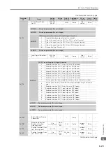
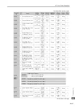
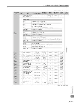
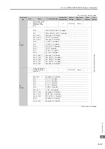
Pn853
2
Latch Sequence 5 to 8
Settings
0000h to
3333h
–
0000h
Rotary
Immedi-
ately
Setup
*2
Pn860
2
SVCMD_IO Input Signal
Monitor Allocations 1
0000h to
1717h
–
0000h
Rotary
Immedi-
ately
Setup
*2
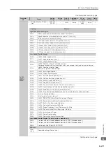
Continued on next page.
Continued from previous page.
Parameter
No.
Size
Name
Setting
Range
Setting
Unit
Default
Setting
Applicable
Motors
When
Enabled
Classi-
fication
Refer-
ence
n.
X
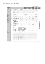
Latch Sequence 5 Signal Selection
0
Phase C
1
EXT1 signal
2
EXT2 signal
3
EXT3 signal
n.
X
Latch Sequence 6 Signal Selection
0 to 3
The settings are the same as those for the Latch Sequence 5 Signal Selec-
tion.
n.
X
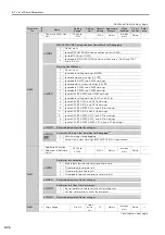
Latch Sequence 7 Signal Selection
0 to 3
The settings are the same as those for the Latch Sequence 5 Signal Selec-
tion.
n.X
Latch Sequence 8 Signal Selection
0 to 3
The settings are the same as those for the Latch Sequence 5 Signal Selec-
tion.
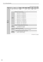
M3
*8
n.
X
Input Signal Monitor Allocation for CN1-13 (SVCMD_IO)
0
Allocate bit 24 (IO_STS1) to CN1-13 input signal monitor.
1
Allocate bit 25 (IO_STS2) to CN1-13 input signal monitor.
2
Allocate bit 26 (IO_STS3) to CN1-13 input signal monitor.
3
Allocate bit 27 (IO_STS4) to CN1-13 input signal monitor.
4
Allocate bit 28 (IO_STS5) to CN1-13 input signal monitor.
5
Allocate bit 29 (IO_STS6) to CN1-13 input signal monitor.
6
Allocate bit 30 (IO_STS7) to CN1-13 input signal monitor.
7
Allocate bit 31 (IO_STS8) to CN1-13 input signal monitor.
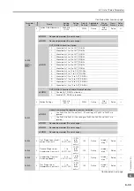
n.
X
CN1-13 Input Signal Monitor Enable/Disable Selection
0
Disable allocation for CN1-13 input signal monitor.
1
Enable allocation for CN1-13 input signal monitor.
n.
X
Input Signal Monitor Allocation for CN1-7 (SVCMD_IO)
0 to 7
The settings are the same as the CN1-13 allocations.
n.X
CN1-7 Input Signal Monitor Enable/Disable Selection
0
Disable allocation for CN1-7 input signal monitor.
1
Enable allocation for CN1-7 input signal monitor.


