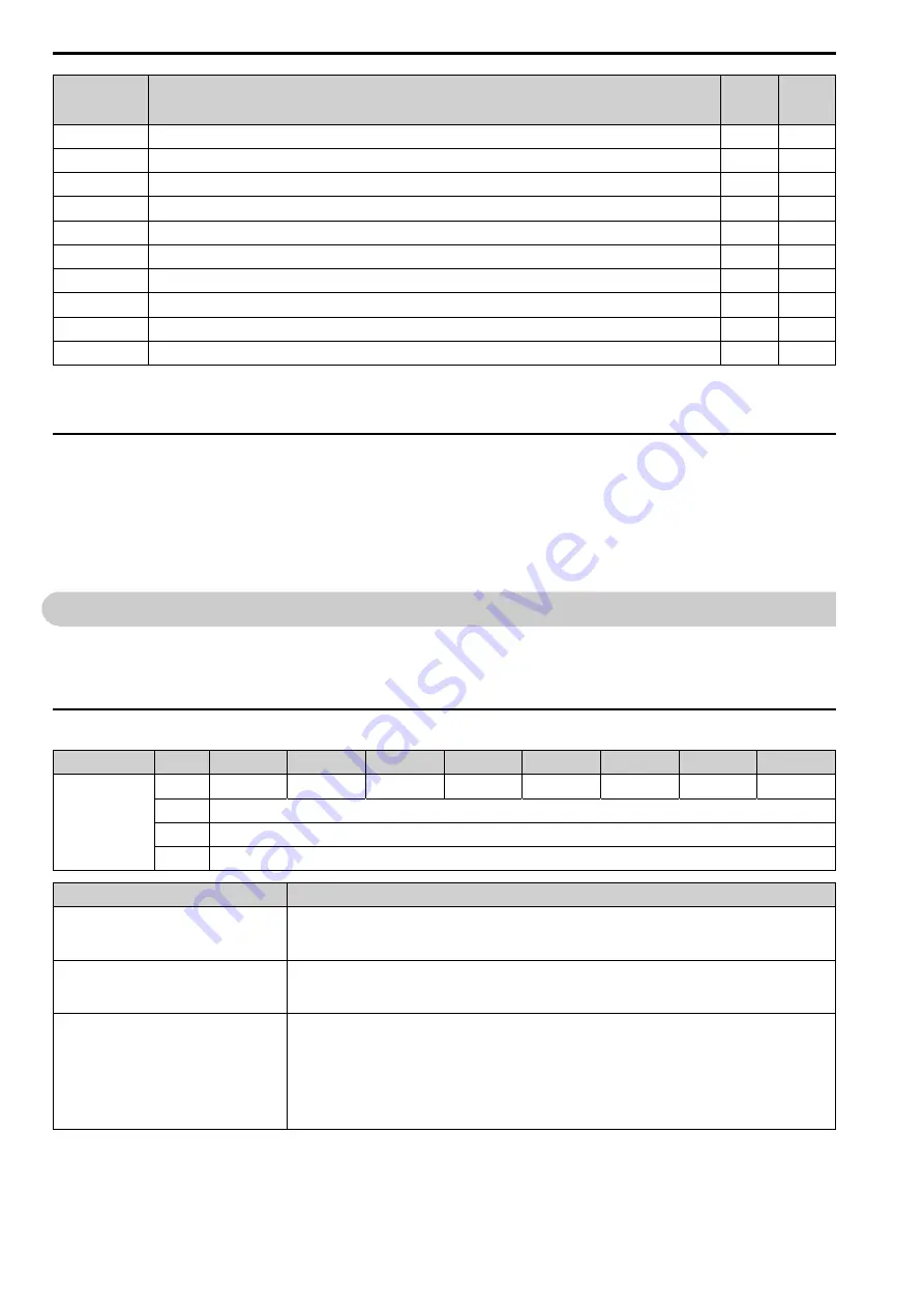
8 Output Assemblies (Drive Consumes)
32
YASKAWA
SIEP C730600 84G DeviceNet Technical Manual
Assembly
Number
(Hex.)
Description
Type
Bytes
150 (96)
MEMOBUS Message Reply (Vendor Specific Yaskawa Electric (YE) Assy)
PPA
5
151 (97)
Standard Status 1 (Vendor Specific Yaskawa Electric (YE) Assy)
PPA
8
152 (98)
Standard Status 2 (Vendor Specific Yaskawa Electric (YE) Assy)
PPA
8
155 (9B)
Enhanced Speed Status, Dynamic (Vendor Specific Yaskawa Electric (YE) Assy)
PPA
8
156 (9C)
Enhanced Control Status (Vendor Specific Yaskawa Electric (YE) Assy)
PPA
8
157 (9D)
Standard DI/DO Status (Vendor Specific Yaskawa Electric (YE) Assy)
PPA
8
158 (9E)
Enhanced Torque Status, Dynamic (Vendor Specific Yaskawa Electric (YE) Assy)
PPA
8
159 (9F)
Dynamic Input Assembly (Vendor Specific Yaskawa Electric (YE) Assy)
PPA
8
160 (A0)
3-Wire Control Status2 (Vendor Specific Yaskawa Electric (YE) Assy)
PPA
4
199 (C7)
Change of State Response (Vendor Specific Yaskawa Electric (YE) Assy)
PPA
8
*1
The drive is compatible with option software versions 1107 and later.
*2
The drive is compatible with option software versions 1111 and later.
*3
The drive is compatible with option software versions 1114 and later.
◆
Additional Support for Setting Connection Path Types
The option can set the produced connection path and the consumed connection path with supported application
tools.
Class 5, Instance 2, Attributes (100, 101) allow setting connection path with a single byte.
For instance, to set the consumed connection path to 100, write 100 (0x64) to Attribute 101. See appendix C of
“
The CIP Networks Library, Volume 1
”
for more information on CIP segments.
8
Output Assemblies (Drive Consumes)
The convention in this manual is from the PLC perspective. An assembly is called an
“
Output Assembly
”
when
outputted from the PLC and received by this node. An
“
Input Assembly
”
is outputted from this node and read by
the PLC. This section details
“
Output Assemblies
”
that are
“
Consumed
”
by the drive.
◆
Basic Speed Control Output - 20 (0x14)
Output Instance
Byte
Bit 7
Bit 6
Bit 5
Bit 4
Bit 3
Bit 2
Bit 1
Bit 0
20
0
-
-
-
-
-
Fault Reset
-
Run Fwd
1
-
2
Speed Reference (Low Byte)
3
Speed Reference (High Byte)
Name
Description
Run Fwd
Forward Run Command
0: Stop
1: Forward run
Fault Reset
Fault Reset
0: -
1: Fault Reset
Speed Reference
Speed Reference
Sets drive speed reference.
Speed reference data: Frequency reference/2
SS
(SS: Speed scale)
Setting range: 0 - 0xFFFF
For example, when setting a reference of 1024 with a speed scale of 2
Speed reference data = 1024/2
2
= 256 = 0x0100
Units are determined by parameter
o1-03 [Frequency Display Unit Selection]
.


