


7 DSP301 and DSP402 Specifications
YASKAWA EUROPE GMBH
YEU SIEP C710616 86A - AC Drive A1000 Option Powerlink - Technical Manual
15
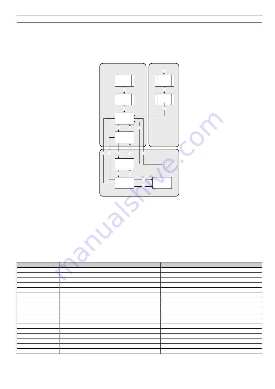
DSP402 State Machine
The state machine of the inverter is described in the CANopen DSP402 specification.
CANopen DSP402 State Diagram
At any time the Powerlink
option card will be in one of the following states. The events that are able to trigger a transition between the states are
either sent with the control word or triggered by an internal action. All the possible events and the corresponding transition number are listed in
.
Figure 6
Figure 6 DSP402 State Diagram
Transition 16 is only available while the drive is performing the quick stop action. When completed, transition will automatically be processed.
CANopen DS402 State Transition Definition
The YASKAWA Powerlink option must be in the state Operation Enable in order to accept frequency and operation commands. In
the
events needed to change between different states are described. Some events are internally triggered, but most of the events are triggered from the
control word received from the bus.
CANopen DSP402 Event Description
The following state transitions are available in the CANopen DSP402 drive profile. Transition 0 and 1 are triggered at start-up and when all start-up
tests are performed the module will be in state 3. Some commands like fault reset can be triggered from more then one place. For example, the reset
command can be triggered both from the bus with the control word, or from the application drive.
Table 7 Event description table
State Transition Number
Transition Name
DSP402 Event
0
Startup => Not Ready To Switch On
Reset
1
Not ready to switch on => Switch on disabled
Self test and init successful
2
Switch on disabled => Ready to switch on
Shutdown command received
3
Ready to switch on => Switched on disabled
Switch on command received
4
Switched on => Operation enabled
Enable operation command received
5
Operation enabled => Switched on
Disable operation command received
6
Switched on => Ready to switch on
Shutdown command received
7
Ready to switch on => Switch on disabled
Quickstop command received
8
Operation enabled => Ready to switch on
Shutdown command received
9
Operation enabled => Switch on disabled
Disable voltage command received
10
Switched on => Switch on disable
Disable voltage or quickstop command received
11
Operation enabled => Quick stop active
Quickstop command received
12
Quick stop active => Switch on disabled
Quickstop completed or Disable voltage command received
13
All states => Fault reaction active
Fatal fault has occurred in the drive
14
Fault reaction active => Fault
The fault action is completed
15
Fault => Switch on disabled
Fault reset command received
16
Quick stop active => Operation enabled
Enable operation command received
Start
Not Ready to
Switch On
Switch On
Disabled
Ready to Switch
On
Switched On
Operation Enable
Quick Stop Active
Fault
Reaction
Active
Fault
0
1
14
13
2
7
3
6
4
5
10
11
16
8
9
12
Power
Disabled
Fault
15
Power
Enabled


