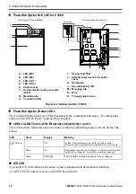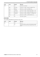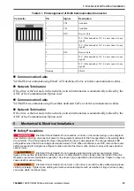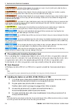
5 Mechanical & Electrical Installation
24
YASKAWA
TOEPC71061687B Powerlink Option Installation Manual
◆
Installing the Option on a Q2A
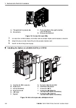
A - Insertion for CN5 connector
B - Option card
C - Screws (included)
D - Drive front cover
E -
LED label
F -
Keypad
G - Option terminal block (CN1)
H - USB port board
I -
Connector CN5-A
J -
Connector CN5-B (Not for
communication option installation)
K - Connector CN5-C (Not for
communication option installation)
Figure 5.12 Q2A Components with Option Card
The procedures for removing and re-attaching the front cover of the inverter drives, and for
removing the USB port board, differ by model. For detailed information please refer to the
Technical Manual of the inverter drive. Communication option cards can only be inserted into
the
CN5-A
connector located on the drive control board.


