


4.2
Using the Functions
189
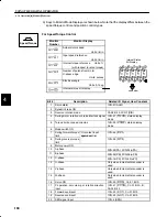
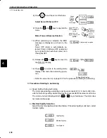
3) User Constants Automatically Settable with Autotuning
Speed/Torque
Positions
Speed/torque
control
Position control
Cn-04
Speed loop gain
Speed loop integration time
constant
Position loop gain
Cn-05
Cn-1A
Cn-04
Speed loop gain
Speed loop integration time
constant
Cn-05
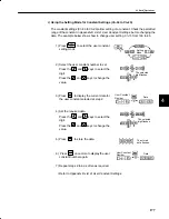
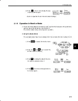
Once autotuning has been completed, the autotuning procedure can be omitted for sub-
sequent machines, providing the machine specifications remain unchanged.
It is sufficient to directly set the user constants for subsequent machines.
The
machine rigidity
can be selected from one of seven levels.
NOTE
•
Conduct autotuning with the motor attached to the machine.
Make sure that the machine is ready for operation and take sufficient safety precautions
when operating the machine.
•
Make sure that the P-CON signal is OFF (PI control is selected) before starting autotun-
ing.
•
Before conducting autotuning, make sure that setting of user constant Cn-10 is 500
(factory setting).
•
Make sure that the speed control mode is set to PI control before starting autotuning.
If the mode switch is used, PI control automatically switches to P control above a set
operating level (PI control to P control switching level), even if the P-CON signal is OFF.
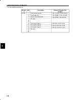
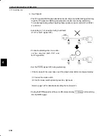
If the mode switch is used, follow operation a) or operation b) below before starting au-
totuning.
a) Set the user constants to disable the mode switch.
Speed control: Set both Cn-01 Bit C and Bit D to 1.
Position control: Set both Cn-01 Bit B to 1.
b) Increase the operating level, such that P control is not selected.
In practice, set the operating level as shown in the table below.
TERMS
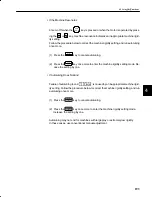
Machine Rigidity
The machine rigidity is one of the machine charac-
teristics related to servo control. Set the servo to
high response for a machine, such as a machine
tool, with high rigidity, and to low response for a ma-
chine, such as a robot, with low rigidity.
High rigidity
Motor
Low rigidity
Motor
4


