


8
Cable Wiring
8.1
Disassembly and Reassembly of the Internal Wiring Harness
8-8
HW1484673
HW1484673
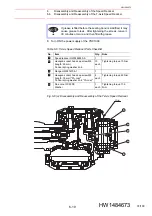
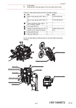
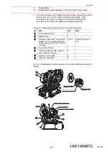
Reassembly
1. Connector base
fig. 8-5 “Disassembly and Reassembly of the Internal Wiring
and
table 8-5 “Internal Wiring Harness Parts
.
1. Put the internal wiring harness through the manipulator from the top
part of the S-head.
2. Connect the connector of the connector base box
3. Connect [LAMP] sticking out from the connector which is inserted into
4CN of the 1BC connector with the connector sticking out from the
internal wiring harness.
4. Mount the saddle
and the saddle
on the internal wiring harness.
Mount the internal wiring harness to the support with hexagon socket
head cap screws
and hexagon socket head cap screws
, and
then tighten with the tightening torque shown in
Wiring Harness Parts Checklist (Connector Base)”
.
5. Mount the connector base B
with the hexagon socket head cap
screws
, and then tighten them with the tightening torque shown in
.
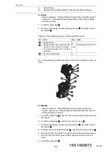
6. Mount the connector for the internal user I/O wiring harness together
with the gasket
on the connector base, and then tighten it with pan-
head sems screws
.
7. Connect the 1BC connector.
8. Mount the ground lead wire by using the cross head APS bolts
.
9. Cover the connectors with the tube
, and then tie the openings of
the tube
by using the cable tie
.
10. Connect the grease hose to the back side of the connector base unit.
11. Mount the cross head APS bolts
, and then mount the connector
base on the manipulator.
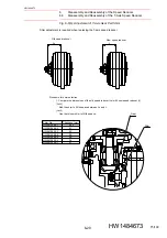
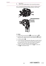
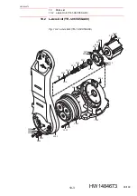
2. S-head
fig. 8-4 “Disassembly and Reassembly of the Internal Wiring
table 8-4 “Internal Wiring Harness Parts
1. Mount the saddle
on the internal wiring harness, and then fasten it
with the hexagon socket head cap screws
with the tightening
torque shown in
.
2. Fix the cover
to the internal wiring harness by using the cable ties
.
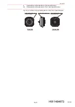
3. Connect the “IN” port and the “OUT” port of the multi-port connector of
the S-head to the “IN” connector and the “OUT” connector of the
internal wiring harness respectively.
4. Fix together the “IN” and “OUT” lead wires of the internal wiring
harness and the lead wires for the encoder of the S- and L-axis by
using the cable ties
.
5. Mount the cover
by using the cross head APS bolts
, and tighten
them with the tightening torque shown in
9
11
8
10
7
6
4
3
2
5
5
12
1
2
3
1
6
7
4
5
85/109