YASKAWA MECHATROLINK-II V1000 Скачать руководство пользователя страница 20

5  Installation Procedure

20


YASKAWA ELECTRIC

 TOBP C730600 49A V1000 Option MECHATROLINK-II Installation Manual

4.

Reattach the


bottom cover.

5.

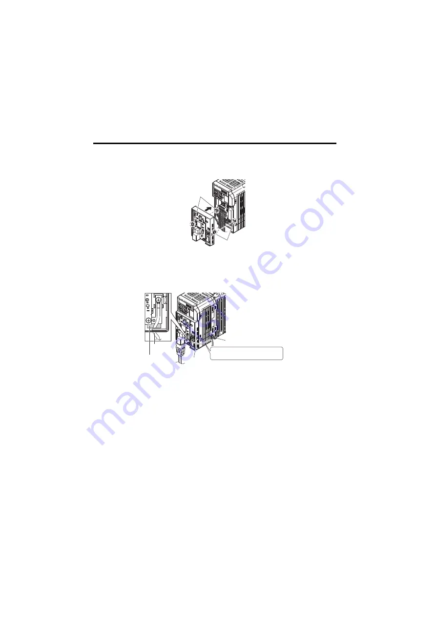
Connect the MECHATROLINK-II Option to the drive. Properly secure the tabs on 
the left and right sides of the MECHATROLINK-II Option to the drive case.

Figure 9

Figure 9  Attach MECHATROLINK-II Option

6.

Connect the ground cable from the drive ground terminal to the MECHATROLINK-II 
Option ground. When wiring the MECHATROLINK-II Option, pass the ground cable 

through the inside of the drive bottom cover, then pass the ground cable into the 

through-hole at the front of the MECHATROLINK-II Option.

Figure 10

Figure 10  Ground Cable Connection

7.

Connect the communications cable to the connector.

Tabs should line up

Tabs should line up

Ground cable

Drive ground terminal

Pass the ground cable through
the bottom cover of the drive.

Through-hole
for ground cable

Ground 
cable

Содержание MECHATROLINK-II V1000

Страница 1: ...YASKAWA AC Drive V1000 Option Installation Manual Type SI T3 V To properly use the product read this manual thoroughly and retain for easy reference inspection and maintenance Ensure the end user rec...

Страница 2: ...This Page Intentionally Blank...

Страница 3: ...INK II Installation Manual 3 Table of Contents 1 PREFACE AND SAFETY 5 2 PRODUCT OVERVIEW 10 3 RECEIVING 11 4 MECHATROLINK II OPTION COMPONENTS 12 5 INSTALLATION PROCEDURE 15 6 MECHATROLINK OPTION DRIV...

Страница 4: ...or written permission of Yaskawa No patent liability is assumed with respect to the use of the information contained herein Moreover because Yaskawa is constantly striving to improve its high quality...

Страница 5: ...sive or sole safety control Without exception all controls should be designed to detect faults dynamically and fail safely under all circumstances All systems or equipment designed to incorporate a pr...

Страница 6: ...before operation To obtain instruction manuals for Yaskawa products access the site below http www e mechatronics com V1000 Series AC Drive Quick Start Guide This guide is packaged together with the...

Страница 7: ...unit The option unit must be installed according to this manual and local codes The following conventions are used to indicate safety messages in this manual Failure to heed these messages could resul...

Страница 8: ...al When ordering a new copy of the manual due to damage or loss contact your Yaskawa representative or the nearest Yaskawa sales office and provide the manual number shown on the front cover DANGER He...

Страница 9: ...coupure de l alimentation pour permettre la decharge des condensateurs Pour repondre aux exigences s assurer que le neutre soit relie a la terre pour la serie 400V WARNING Read manual before installin...

Страница 10: ...MECHATROLINK protocol By installing the MECHATROLINK II Option to a drive it is possible to do the following from a MECHATROLINK master device operate the drive monitor the operation status of the dri...

Страница 11: ...el by checking the information on the nameplate see Figure 1 If you have received the wrong model or the MECHATROLINK II Option does not function properly contact your supplier Contents and Packaging...

Страница 12: ...Cables are not connected to the MECHATROLINK II Option and are packaged separately in the box I Connector B LED ERR red J MECHATROLINK II PCB C LED TX green K Attachment screw hole for option cover D...

Страница 13: ...ds 27 mm to the total depth of the drive Figure 2 Figure 2 Dimensions Connector Table 3 Connector Descriptions Connector Pin No Signal Name I O Function CN3 A1 NC Not used A2 SRD I O Send receive data...

Страница 14: ...rive or SI T3 V has no power An internal self diagnostic error occured in the SI T3 V ERR ON Connection error SI T3 V is not properly connected to the drive Communication error Flashing SI T3 V error...

Страница 15: ...ot remove option cover while the power is on Failure to comply could result in death or serious injury The diagrams in this section may include option units and drives without covers or safety shields...

Страница 16: ...d equipment Failure to comply may cause further damage to the equipment Do not connect or operate any equipment with visible damage or missing parts Do not use unshielded cable for control wiring Fail...

Страница 17: ...inal on the MECHATROLINK II Option is supplied with a ground cable that should be connected to the ground terminal on the drive If there are noise influences on communication remove the grounding cabl...

Страница 18: ...stallation 1 Switch off the power supply to the drive DANGER Electrical Shock Hazard Do not connect or disconnect wiring while the power is on Failure to comply will result in death or serious injury...

Страница 19: ...rom the MECHATROLINK II Option kit depending on drive size Figure 7 Figure 7 Ground Cable Note Remove the terminal cover 1 before removing the bottom cover to install the MECHATROLINK II Option Replac...

Страница 20: ...ground cable from the drive ground terminal to the MECHATROLINK II Option ground When wiring the MECHATROLINK II Option pass the ground cable through the inside of the drive bottom cover then pass the...

Страница 21: ...on the front of the MECHATROLINK II Option MECHATROLINK II Communications Cables Wire the MECHATROLINK II communications cables to the communications connector CN3 Install MECHATROLINK II communicati...

Страница 22: ...op Decelerate to stop using the deceleration time in C1 02 1 Coast to stop 2 Fast Stop Decelerate to stop using the deceleration time in C1 09 3 Alarm only 1 F6 02 Selection of External Fault from Com...

Страница 23: ...02 to 3 To control the frequency reference of the drive via the master device set b1 01 to 3 2 If set to 3 then the drive will continue to operate when a fault is detected Take proper measures such as...

Страница 24: ...Did a momentary power loss interrupt communications Table 6 Fault Display and Possible Solutions LED Operator Display Fault Name bUS MECHATROLINK II Option Communication Error After establishing initi...

Страница 25: ...is being sent from the master controller PLC Remove the cause of the external fault Reset the external fault input from the PLC device Problem with the PLC program Check the program used by the PLC a...

Страница 26: ...I Option Contact Yaskawa for assistance LED Operator Display Fault Name oFA04 MECHATROLINK II Option Fault MECHATROLINK II Option Flash write mode Cause Possible Solution MECHATROLINK II Option hardwa...

Страница 27: ...cified range YES LED Operator Display Minor Fault Name CALL Serial Communication Transmission Error Communication has not yet been established Cause Possible Solution Minor Fault H2 10 Communication w...

Страница 28: ...is an MP2300 x For MECHATROLINK II 32 byte transmission 2 0 ms communications cycle 21 stations max 21 stations can be set but then the maximum number of connectable drives will be 16 x For MECHATROL...

Страница 29: ...f Publication Rev No Section Revised Content February 2014 Back cover Revision Address May 2013 Back cover Revision Address November 2011 Front cover back cover Revision Format September 2010 Back cov...

Страница 30: ...oad HuangPu District Shanghai 200003 China Phone 86 21 5385 2200 Fax 86 21 5385 3299 http www yaskawa com cn YASKAWA ELECTRIC CHINA CO LTD BEIJING OFFICE Room 1011 Tower W3 Oriental Plaza No 1 East Ch...

Отзывы: