2.9 n: Special Adjustments
YASKAWA ELECTRIC
TOEP C710687 03B FSDrive-MV1000 Parameter Guide
227
n
Current Detection for the Commercial Power Supply
To use the Synchronous Transfer, a current detector must be installed on the commercial power supply side of the drive.
The connection to the drive is made to the input current detection circuit (option) through the external terminals.
The methods that are used to monitor and adjust the current value is the same as for the input current detection.
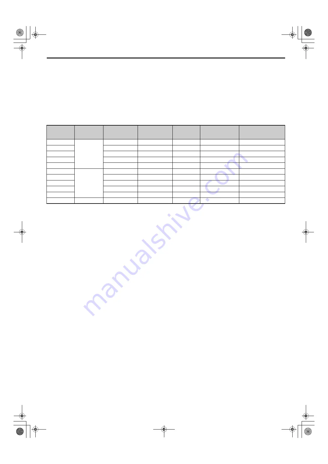
Table 2.29 CTs for Commercial Power Supply Current Detection,
Resistor Boards, and Parameter Settings for Current Detection
• Connect the CT to C21 (phase R) and CN22 (phase T) on the CNT board (2 connections).
• Connect the resistor board (13PCB) to CN23 on the CNT board (1 connection).
• The current direction for the CT is positive for the motor side (mount the CT in the correct orientation).
• An input resistor must install and set parameters according to the selected CT.
• n9-71 (Input Current Conversion Coefficient) =
CT rated output current (A) / CT rated input current (A)
×
Input resistance (
Ω
)
Example of calculation for a 35 A Power Cell: n9-71 = 0.1 A / 200 A
×
68
Ω
= 0.0340
n
Precautions for Using the Synchronous Transfer
• The Synchronous Transfer cannot be applied to a commercial power supply if it has a different voltage from the rated
voltage of the drive.
• Select a reactor with an impedance of about 3 to 7%.
• Make sure the output voltage is high enough based on the output current and the impedance of the reactor when the
transfer is made.
• Make sure the main circuit power supply is wired in phase with the drive.
If the Synchronous Transfer command is issued and the phase is connected in reverse, an error will be detected.
• Make sure that the main circuit wiring and voltage detection phases match the phases on the drive and the commercial
power supply (U = R, V = S, W = T).
• Always input the close signal (answer) for the drive secondary side breaker. If there are any wiring problems, an error
will be detected.
• Assign the necessary functions to the multi-function contact outputs. If there are any wiring problems, an operation
error will be detected (H1-02 to H1-16: 82H and 83H, H2-01 to H2-16: 40H (141H) and 41H (140H)).
• When the input for the Synchronous Transfer command is on, operate the breaker according to the drive commands. If
the breaker performs an operation that does not match the command, an error will be detected.
• To discontinue the Synchronous Transfer process, make sure to turn off the Run command.
• Do not turn off the Synchronous Transfer command until the completion signal for Synchronous Transfer is output, or
until the motor stops.
• If the Synchronous Transfer command is turned off after the completion signal for Synchronous Transfer is output, the
following commands will all turn off: close command for commercial power supply side breaker, close command for
drive secondary side breaker, and completion signal for Synchronous Transfer.
• When the main circuit power supply to the drive is turned off, do not close the breaker on the output side of the drive.
If power is supplied to the output side of the drive, it may damage the drive.
<1> The input current detection circuit on the drive is used and therefore it cannot be used to detect input current of the drive.
Rated Current
A
CT Type
CT Rated Input
Current
A
CT Rated Output
Current
mA
Input
Resistance
Ω
Resistance Board
Code
Setting of n9-71 (Input
Current Conversion
Coefficient)
35
LA205-S
200
100
68.00
JEBC-61902-7
0.0340
50
200
100
68.00
JEBC-61902-7
0.0340
70
200
100
47.00
JEBC-61902-1
0.0235
100
200
100
30.00
JEBC-61902-2
0.0150
140
200
100
22.00
JEBC-61902-4
0.0110
200
LT505-S
500
100
47.00
JEBC-61902-1
0.0094
260
500
100
30.00
JEBC-61902-2
0.0060
330
500
200
15.00
JEBC-61902-5
0.0060
400
500
200
10.00
JEBC-61902-8
0.0040
520
500
200
10.00
JEBC-61902-8
0.0040
650
LT1005-S
1000
200
15.00
JEBC-61902-5
0.0030
MV1000ParameterGuide_E_conditional.book 227 ページ 2013年10月11日 金曜日 午後8時18分


