3.5 Mounting Interval
3.5.1 Installing One SERVOPACK in a Control Panel
3-7
3
Installation
3.5
Mounting Interval
3.5.1
Installing One SERVOPACK in a Control Panel
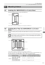
Provide the following spaces around the SERVOPACK.
*
For this dimension, ignore items protruding from the main body of the SERVOPACK.
3.5.2
Installing More Than One SERVOPACK in a Control
Panel
Provide the following intervals between the SERVOPACKs and spaces around the SERVO-
PACKs.
*
For this dimension, ignore items protruding from the main body of the SERVOPACK.
The space required on the right side of a SERVOPACK (when looking at the SERVOPACK from
the front) depends on the SERVOPACK models. Refer to the following table.
30 mm min.
30 mm min.
40 mm min.
*
40 mm min.
SERVOPACK
Install cooling fans above the SERVOPACKs so that hot spots do not occur around the SERVO-
PACKs. Provide sufficient intervals and spaces as shown in the following figure to enable cooling
by the fans and natural convection.
SERVOPACK Model
Space on
Right Side
Cooling Fan Installation Conditions
10 mm above SERVOPACK’s Top Surface
SGD7S-
R70A, R90A, 1R6A, 2R8A,
3R8A, 5R5A, 7R6A, R70F,
R90F, 2R1F, 2R8F
1 mm min.
Air speed: 0.5 m/s min.
120A, 180A, 200A, 330A,
470A, 550A, 590A, 780A
10 mm min.
Air speed: 0.5 m/s min.
Important
Fan
30 mm min. This distance depends
on the model.
30 mm min.
Fan
40 mm min.
*
40 mm min.
SERVOPACK
SERVOPACK
SERVOPACK
SERVOPACK

