background image

model no. 

060-1314-4

  |  contact us: 1.866.523.5218

model no. 

060-1314-4

  |  contact us: 1.866.523.5218

30

CONTRO

lS

 

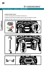
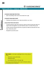
WARNING: If snow clogs the discharge chute do not try to remove it 

before:


Releasing the auger control handle.


Stopping the engine.


Disconnecting the cable from the spark plug.

Do not put your hand inside the chute or auger. Use the chute clearing 
tool included with your snowblower. 

CHANGe DISCHARGe DIReCTION:
1.  Move the discharge chute rotation lever either left or right.

CHANGe DISCHARGe HeIGHT:
1.  Discharge chute deflector lever controls the deflector up or down.

ADJUSTING THe SNOW SHOeS


Tilt the snowblower auger back and place a spacer under the shave plate below the 

augers that is the height that you want the shave plate to ride above the ground.


Loosen the bolts holding the skid shoes in place and slide the skid shoes down until 

they contacts the ground.


Re-tighten the skid shoe bolts.

Содержание 100666

Страница 1: ...us 1 866 523 5218 Snowblower IMPORTANT Please read this manual carefully before operating this snowblower and save it for reference WARNING Machine is without engine oil Properly fill engine oil prior...

Страница 2: ...IONS 11 ASSEMBLY 14 OPERATION 20 STARTING THE ENGINE 24 CONTROLS 27 MAINTENANCE 31 FIG A SNOWBLOWER PARTS DIAGRAM 34 FIG A PARTS LIST SNOWBLOWER 35 FIG B ENGINE DIAGRAM 36 FIG B PARTS LIST ENGINE 37 F...

Страница 3: ...disengage the controls quickly Never allow children under 16 years old to operate the equipment Never allow adults to operate the equipment without proper instruction Thrown objects can cause serious...

Страница 4: ...osed spaces Never remove gas cap or add fuel while the engine is hot or running Allow engine to cool at least two minutes before refueling Do not over fill fuel tank Keep fuel level at least 1 27 cm b...

Страница 5: ...nded disengage all control levers stop the engine and remove the safety key Do not run the engine indoors Exhaust fumes are dangerous Do not clear snow across the face of slopes Exercise extreme cauti...

Страница 6: ...arts in the auger housing CLEARING A CLOGGED DISCHARGE CHUTE Hand contact with the rotating impeller inside the discharge chute is the most common cause of injury associated with snowblowers Never use...

Страница 7: ...ill hot Open Flame Alert Fuel and its vapours are extremely flammable and explosive Keep fuel away from smoking open flames sparks pilot lights heat and other ignition sources Electric Shock Failure t...

Страница 8: ...and remain behind handles until all moving parts have stopped before unclogging Hot Surface To reduce the risk of injury or damage avoid contact with any hot surface Risk of Fire Fuel and its vapours...

Страница 9: ...Use clean fresh regular unleaded gasoline with a minimum octane rating of 85 and an ethanol content of less than 10 by volume Fuel Valve ON Move the fuel valve lever to the on position Choke ON To sta...

Страница 10: ...tart a warm engine DO NOT prime Recoil Start Pull the recoil starter grip to start manually Choke OFF When the engine starts move the choke to run position Stop Follow steps to stop Fuel Valve OFF Mov...

Страница 11: ...gine Model R225S Start Type Electric Recoil OIL Oil Capacity 16 9 fl oz 0 5 L Oil Type 0W 30 FUEL Use clean fresh regular unleaded gasoline with a minimum octane rating of 85 and an enthanol content o...

Страница 12: ...ver G Grip Heat Warmer Switch H Clean out Tool I Upper Handle J Discharge Chute Deflector K Discharge Chute L Auger M Shave Plate N Skid Shoes O Auger Housing P Wheels Q Lower Handle R Handle Locking...

Страница 13: ...model no 060 1314 4 contact us 1 866 523 5218 13 Specifications J L M O K I Q P S R N A H I J E F G B C D R...

Страница 14: ...bly TOOLS REQUIRED Part Size Wrench included 13 16 ADDITIONAL PARTS Part Part Qty Usage Shear Pins 4 Spare part preassembled Clip for auger 4 Spare part preassembled Starter Electric Cord 1 Accessory...

Страница 15: ...d locking knobs 2 3 Fig 2 The top handle can adjust to 4 positions You can come back later and adjust to a more comfortable height 2 1 2 2 2 3 Figure 2 3 Remove the chute pivot assembly 3 1 from the b...

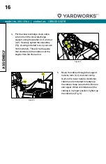
Страница 16: ...r your own 16mm wrench This will be the guide that channels all the cables over the engine from the chute area 4 2 4 1 Figure 4 5 Route the cables through the support rod wire form 5 1 and cord clamp...

Страница 17: ...be used after the 5 hour initial break in period Using synthetic oil does not increase the recommended oil change interval 20 0 20 40 Ambient temperature Recommended Engine Oil Type 28 9 F C 17 8 6 7...

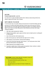
Страница 18: ...rs are explosive Serious personal injury can occur when gasoline is spilled on yourself or your clothes which can ignite If you come into contact with gasoline wash affected areas of skin and change c...

Страница 19: ...efore filling 12 If possible remove gas powered equipment from the truck or trailer and refuel it on the ground If this is not possible then refuel such equipment on a trailer with a portable containe...

Страница 20: ...ring to other people or their property 6 Never use the snowblower under the influence of alcohol or medication or if you are tired or ill PREPARATION FOR USE 1 Thoroughly inspect the area where the eq...

Страница 21: ...eep it away from the plug to prevent accidental starting 7 Before leaving the machine unattended disengage all control levers stop the engine and remove the safety key 8 Do not run the engine indoors...

Страница 22: ...Be careful while working on the machine or clearing a blockage in the auger or impeller to ensure that fingers and hands do not become crushed or cut 23 Do not touch hot engine components like the mu...

Страница 23: ...stand on level ground when checking Engine key may be attached to the recoil starter grip Please remove the key from the recoil starter grip and attach install properly BEFORE OPERATION CHECK THE GEN...

Страница 24: ...Move the fuel shut off lever 10 3 to the ON position 2d Prime 3 5 times 2e Move the choke lever 10 2 to the run position once the engine begins to run after you pull the recoil start grip or use the e...

Страница 25: ...ectric start button and make sure that the main supply voltage is 120 V 60 Hz Fig 13 Figure 13 CAUTION To prevent damaging the electric starter do not run it more than 10 times at intervals of 5 secon...

Страница 26: ...ues other than the natural power loss we can provide a high altitude carburetor main jet at an additional cost The part number and recommended minimum altitude for the application of the high altitude...

Страница 27: ...wblower When the snowblower has been put into gear pushing this lever towards the handle engages the wheels Releasing the self drive control lever causes the machine to stop moving SPEED CONTROL LEVER...

Страница 28: ...m behind the snowblower Pushing this lever towards the handle causes the auger and impeller to activate Releasing the auger control lever causes the auger to stop moving Discharge chute deflector leve...

Страница 29: ...n CLUTCH LOCK FEATURE This snowblower offers a clutch lock feature that will enable the operator to keep the snowblower moving forward while you adjust the chute To use the clutch lock system follow t...

Страница 30: ...tool included with your snowblower CHANGE DISCHARGE DIRECTION 1 Move the discharge chute rotation lever either left or right CHANGE DISCHARGE HEIGHT 1 Discharge chute deflector lever controls the defl...

Страница 31: ...e machine is to be stored for a longer period than 30 days the following procedures are recommended 1 Mix fuel stabilizer with gasoline according to fuel stabilizer manufacturer s directions 2 Start t...

Страница 32: ...6 months or 100 hrs Every year or 150 hrs Engine Oil Check level Change Spark Plug Check Clean Replace Spark Arrester optional parts Clean Idle Speed Check adjust 1 Valve Clearance Check adjust 1 Fuel...

Страница 33: ...model no 060 1314 4 contact us 1 866 523 5218 33 This page intentionally left blank...

Страница 34: ...1314 4 contact us 1 866 523 5218 34 FIG A SNOWBLOWER PARTS DIAGRAM 1 Figure E Figure A 2 2 3 4 5 6 7 Figure D 6 5 3 4 13 Figure F 10 8 9 12 11 24 Figure B 23 22 21 14 14 14 16 19 16 12 12 15 17 17 18...

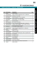
Страница 35: ...Screw M6 16 White Zinc 2 10 23016000135000A Auger Belt Gates 5LXA935E L W H 935 16 6 8 2 1 11 2303600007A Drive Belt Megadyne HTD 840 5M15 L W 840 15 Pitch 5 mm 1 12 30133020035000 Flange Triangle Se...

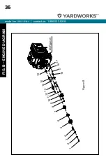
Страница 36: ...model no 060 1314 4 contact us 1 866 523 5218 36 FIG B ENGINE DIAGRAM 1 2 3 4 5 6 7 8 9 10 11 12 13 14 15 19 16 17 18 17 20...

Страница 37: ...gon Blue White Zinc 1 9 23034000565000A Shaft Sheath Thin Small Tension Pulley 18 6 1 10 23034000665000A Small Tension Pulley 55 22 6 1 11 23034000575000A Shaft Sheath Small Tension Pulley 18 16 5 1 1...

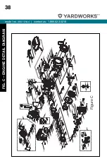
Страница 38: ...27 28 29 30 31 32 33 34 35 36 37 38 39 40 41 42 43 45 46 47 48 49 50 51 52 53 54 55 56 57 57 58 59 60 61 61 62 63 64 65 66 67 68 69 70 71 72 73 74 75 74 76 77 78 79 80 82 83 84 85 86 87 88 90 91 92 9...

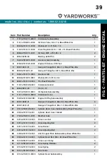
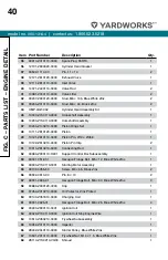
Страница 39: ...e Gasket 1 15 90502 0812 00 Pin 8 12 2 16 15010 Z1S0110 0B01 Oil Dipstick Subassembly 1 17 11411 Z1S0110 0B00 Crankcase Cover 1 18 15030 Z010130 OB01 Engine Oil Plug Subassembly 1 19 90001 0832 01 Hex...

Страница 40: ...0 Piston Pin 13 45 9 1 50 13122 Z510210 0000 Piston Pin Clip 2 51 13010 Z810210 0000 Connecting Rod 1 52 30360 Z330110 H301 Support Control Box Subassembly 1 53 90001 0512 01 Hexagon Flange Bolt M5 12...

Страница 41: ...2 83 90686 Z010710 0001 Fuel Pipe 4 5 8 5 160 1 84 30431 Z010110 0000 Rubber Jacket 9 5 11 90 Black 1 85 17001 Z010210 0000 Air Cleaner Gasket 1 86 16161 Z151310 0000 Main Jet Standard 1 16161 Z151110...

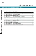
Страница 42: ...0 Z1S0110 0000 Muffler Assembly 1 104 90303 0800 31 Hexagon Flange Nut M8 Blue White Zinc 2 105 18140 Z1S0310 HL02 Scald Resistant Cover 1 106 90001 0616 01 Hexagon Flange Nut M6 16 Blue White Zinc 3...

Страница 43: ...model no 060 1314 4 contact us 1 866 523 5218 43 This page intentionally left blank...

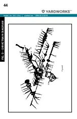
Страница 44: ...218 44 FIG D DRIVETRAIN DIAGRAM 1 2 3 4 5 6 7 8 9 10 11 20 21 22 23 24 25 18 26 27 28 29 21 49 18 18 30 48 40 41 42 43 44 45 46 47 46 12 12 13 14 19 12 13 14 19 39 38 15 16 37 17 36 35 18 34 33 18 32...

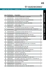
Страница 45: ...23052000205000A Bearing Support T 1 5 White Zinc 4 15 30313090035000 Hexagon Locking Nut M6 Blue White Zinc 6 16 23052000105000A Pressing Plate Bearing T 1 5 mm 2 17 A26800409101 Bearing 25 4 52 15 2...

Страница 46: ...Welded Assembly 1 40 23033000365000A Wheeled Six Party Shaft 19 323 40Cr Black 1 41 30823040015000 Elastic Column Pin 3 30 Black 2 42 30423010065000 Shaft Elastic Circlip 35 Black 1 43 2303200062A Shi...

Страница 47: ...model no 060 1314 4 contact us 1 866 523 5218 47 This page intentionally left blank...

Страница 48: ...contact us 1 866 523 5218 48 FIG E AUGER DIAGRAM 1 2 3 4 5 6 7 8 9 10 11 12 13 14 15 5 7 9 5 6 7 1 2 3 4 16 17 18 19 20 42 43 19 18 21 22 23 24 25 26 3 16 28 29 30 31 32 33 34 35 27 41 40 36 37 38 39...

Страница 49: ...uare Neck Bolt M8 16 Blue White Zinc 4 16 30323060035000 Flange Locking Nut M8 Hexagon Blue White Zinc 9 17 2303200141A Snow Shovel Plate 24 1 18 23041000150243A Skid Shoes 2 19 30913090045000 Half ro...

Страница 50: ...0015000 Small Carriage Bolt M8 40 Blue White Zinc 1 37 23034000555000A Sheath Large Tension Wheel 20 18 3 1 38 23032000105000C Large Tension Pulley 66 5 36 2 1 5 1 39 23034000545000A Sheath Thin Large...

Страница 51: ...model no 060 1314 4 contact us 1 866 523 5218 51 This page intentionally left blank...

Страница 52: ...model no 060 1314 4 contact us 1 866 523 5218 52 FIG F CHUTE DIAGRAM 1 2 6 3 4 5 2 7 8 9 10 11 12 13 14 15 16 18 17 16 17 19...

Страница 53: ...000105000A Guy Wire Plate T 3 mm White Zinc 1 9 30333020025000 Cap Nut M5 Blue White Zinc 1 10 23075000200265A Chute Support Arm 1 11 23063000565000A Special Bolt M10 40 Black Zinc 1 12 23071000240001...

Страница 54: ...ASSEMBLY DIAGRAM 1 2 3 4 5 6 7 8 9 5 11 1 10 10 1 12 11 13 14 11 14 12 11 16 17 18 19 20 15 16 17 18 11 21 12 22 23 24 25 26 21 12 22 23 27 25 26 21 12 22 23 28 25 29 31 32 33 34 35 43 44 36 37 38 39...

Страница 55: ...4 15 23062000830265A Front Adjustment Plate 165 35 1 16 A26800104801 Self tapping Screw ST5 30 Blue White Zinc 2 17 30512050035000 Big Washer 5 Blue White Zinc 2 18 30113010125000 Self tapping Screw...

Страница 56: ...061000480301A Handle Support Unit 2 39 30313090035000 Hexagon Locking Nut M6 Blue White Zinc 2 40 23065000275000A Self locking Plate Assembly Right Trigger 62 5 36 30 Black 1 41 23063000515000A Self l...

Страница 57: ...model no 060 1314 4 contact us 1 866 523 5218 57 This page intentionally left blank...

Страница 58: ...ING DIAGRAM Alternating current AC start cable Right LED lamp ass y B R Engine B R B R B W B R B R B R B R R R B W R BLACK WHITE RED Generator Plug Power outlet wire Left LED lamp ass y Heated handle...

Страница 59: ...model no 060 1314 4 contact us 1 866 523 5218 59 This page intentionally left blank...

Страница 60: ...rotate Foreign material caught in system Clean Auger drive belt slipping Adjust the belt and wire Auger drive belt broken Replace the belt Auger does not stop when the lever is released Auger drive be...

Страница 61: ...kid shoes and shave plate These parts are warranted to the original purchaser to be free from defects in material and workmanship for a period of two hundred seventy 270 days from the date of retail p...

Страница 62: ...or damage including without limitation any indirect incidental consequential or exemplary damages arising in connection with the sale use or inability to use this product NOTICE TO CONSUMER This warr...

Страница 63: ...model no 060 1314 4 contact us 1 866 523 5218 63 This page intentionally left blank...

Страница 64: ...ated part on your engine is defective in materials or workmanship the part will be repaired or replaced by CPE OWNER WARRANTY RESPONSIBILITIES As the small off road engine SORE owner you are responsib...

Страница 65: ...r replaced under the ECS Warranty shall be warranted for the remainder of the ECS Warranty Period 3c Any warranted emissions related part which is scheduled for replacement as required maintenance in...

Страница 66: ...Fuel Tank Fuel Cap Fuel Lines for liquid fuel and fuel vapors Fuel Line Fittings Clamps Pressure Relief Valves Control Valves Control Solenoids Electronic Controls Vacuum Control Diaphragms Control C...

Отзывы: