background image

Содержание 7L3

Страница 1: ...state laws if any If a spark arrester is used it should be maintained in effective working order by the operator In the State of California the above is required by law Section 4442 of the California...

Страница 2: ...dealer MTD LLC YaRD MaN Po Box o CLEVELAND OH 44136 www yardr nan com 330 220 4683 888 888 731 8 Copy the model number here Copy the serial number here CUSTOMER SUPPORT Please doNOTretum theunit to t...

Страница 3: ...ent or repair to protect your eyes Thrown objects which ricochet can cause serious injury to the eyes 3 Do not operate without wearing adequate winter outer garments Do not wear jewelry long scarves o...

Страница 4: ...ENANCE ANDSTORAGE 1 Never tamper with safety devices Check their proper operation regularly Refer to the maintenance and adjustment sections of this manual 2 Before cleaning repairing or inspecting ma...

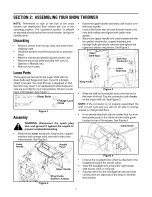
Страница 5: ...washers and carriage bolts from each side of the lower handle See Figure 2 Lower Handle Upper Handle Ning Knobs Washers Bolts Raise the upper handle assembly until it locks over the lower handle Look...

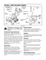
Страница 6: ...ontrol to engage the augers Release to stop the snow throwing action Drive control must also be released See Figure 5 IMPORTANT Refer to Auger Control Teston page 9 prior to operating your snow throwe...

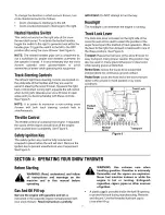
Страница 7: ...re the unit will start Remove the ignition key to prevent unauthorized use of equipment See Figure 5 IMPORTANT Do NOT attempt to turn the key Headlight The headlight is on whenever the engine is runni...

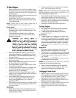
Страница 8: ...ecoilStarter Rotate choke knob to FULL choke position cold engine start If engine is warm place choke in OFF position instead of FULL Push primer button two or three times If engine is warm push prime...

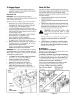
Страница 9: ...adjustment has been achieved Repeat the previous steps to provide more slack in cable if necessary Auger Control _ Jam Auger Control Cable Figure 7 Clean Out Tool The clean out tool is conveniently f...

Страница 10: ...ghest speed With the drive control released push the snow thrower forward The unit should roll forward Then engage the drive control The wheels should stop turning Now release the drive control and pu...

Страница 11: ...ier and sliding the shift rod connector back down into place IMPORTANT Make certain to check for correct adjustment of the shift rod as instructed under Final Adjustments in the Assembly Section befor...

Страница 12: ...amage to the seals could result Be sure the vent plug is free of grease in order to relieve pressure AugerShaft At least once a season remove the shear bolts on the auger shaft Spray lubricant inside...

Страница 13: ...OTE It is necessary to remove both belts in order to change either one If changing just one belt be certain to check the condition of the other belt Remove the plastic belt cover at the front of the e...

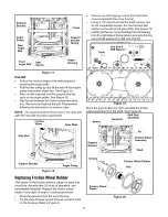
Страница 14: ...ould be checked after 25 hours of operation and periodically thereafter Replace the friction wheel rubber if any signs of wear or cracking are found Drain the gasoline from the snow thrower Tip the sn...

Страница 15: ...o be stored over 30 days prepare for storage as follows Remove gasoline from carburetor and fuel tank to prevent gum deposits from forming on these parts and causing possible malfunction of engine Run...

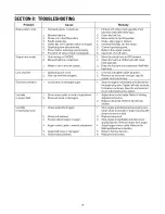
Страница 16: ...stale after thirty days 2 Clean the fuel line 3 Move switch to the ON position 4 Clean adjust gap or replace 5 Insert the key fully into the switch 6 Connect spark plug wire 7 Refer to the engine manu...

Страница 17: ...NOTES 17...

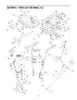
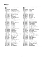
Страница 18: ...SECTION 9 PARTS LISTFORMODEL 7L3 33_ 80 23 31 78 2 5 76 75 J 74 75 13 10_ 72 Part of handle panel for reference only 9 28 11 22 11 19 15 70 18...

Страница 19: ...bly w Tilt Hex Bolt 3 8 24 x 1 5 TT Screw 1 4 20 x 0 5 Clevis Pin Jam Lock Nut 3 8 24 Ref No 43 44 45 46 47 48 49 50 51 52 53 54 55 56 57 58 59 60 61 62 63 64 65 66 67 68 69 70 71 72 73 74 75 76 77 78...

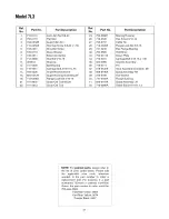
Страница 20: ...Model7L3 15 14 11 12 3 2 22 36 41 37 39 42 2O...

Страница 21: ...605 5196A Auger Housing Assembly 28 39 736 0188 Flange Lock Nut 5 16 18 40 741 0493A Clean Out Tool Mount 41 605 5197A Clean Out Tool 42 710 0890A Part Description Bearing Housing Hex Screw 5 16 12 Ca...

Страница 22: ...Model7L3 26 19 21 16 23 16 16 24 11 10 16 12_ 19 15 18 20 14 3 13 I I I 25 22...

Страница 23: ...5 16 24 x 75 Hex Cap Screw 3 8 16 x 1 25 Drive Clutch Idler Bracket Shoulder Spacer Pulley Half V Belt Pulley Half Bell Washer Hex Cap Screw 1 4 28 x 50 Flat Idler Lock Hex Cap Screw 5 16 24 Lock Jam...

Страница 24: ...Model7L3 22 23 25 19 26 29 27 20 _ 19 4O 41 37 24...

Страница 25: ...Flange Bearing Hex Cap Screw 5 16 18 x 1 Shoulder Spacer Tap Screw 5 16 12 x 750 Frame Assembly Hex Screw 1 4 28 x 375 Cable Roller Drive Cable Guide Bracket Tap Screw 1 4 20 x 5 Shift Frame Bracket...

Страница 26: ...Model7L3 14 2 j3 5 10 16 20 25 48 22 18 30 17 31 15 13 41 56 35 23 37 44 40 30 27 26...

Страница 27: ...Flat Washer Spacer Flange Lock Nut 5 16 18 LH Dogg Assembly Idler Axle Assembly Eye Bolt Track Side Plate Actuator Shaft Chain Ref No 29 30 31 32 33 34 35 36 37 38 39 40 41 42 44 45 46 47 48 49 50 51...

Страница 28: ...eck adjustments and normal deterioration of the exterior finish due to use or exposure Service completed by someone other than an authorized service dealer e f g MTD does not extend any warranty for p...

Отзывы: