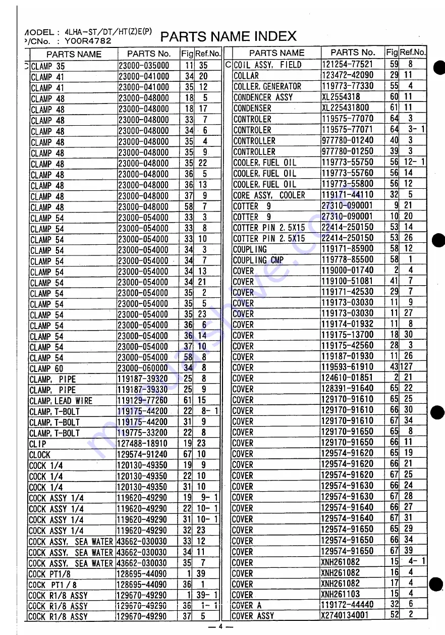
Yanmar 4LHA-HTP Скачать руководство пользователя страница 252

PARTS NAME 

PARTS No.  Fig Ref.No. 

PARTS NAME 

PARTS No.  Fig Ref.No. 

: CLAMP 35 

23000-035000 

11  35 

C COIL ASSY, FIELD 

121254-77521 

59  8 

CLAMP 41 

23000-041000 

34  20 

COLLAR 

123472-42090 

29  11 

CLAMP 41 

23000-041000 

35  12 

COLLER, GENERATOR 

119773-77330 

55  4 

CLAMP 48 

23000-048000 

18  5 

CONDENCER ASSY 

XL2554318 

60  11 

CLAMP 48 

23000-048000 

18  17 

CONDENSER 

XL225431800 

61  11 

CLAMP 48 

23000-048000 

33  7 

CONTROLER 

119575-77070 

64  3 

CLAMP 48 

23000-048000 

34  6 

CONTROLER 

119575-77071 

64  3- 1 

CLAMP 48 

23000-048000 

35  4 

CONTROLLER 

977780-01240 

40  3 

CLAMP 48 

23000-048000 

35  9 

CONTROLLER 

977780-01250 

39  3 

CLAMP 48 

23000-048000 

35  22 

COOLER, FUEL OIL 

119773-55750 

56  12- 1 

CLAMP 48 

23000-048000 

36  5 

COOLER, FUEL OIL 

119773-55760 

56  14 

CLAMP 48 

23000-048000 

36  13 

COOLER, FUEL OIL 

119773-55800 

56  12 

CLAMP 48 

23000-048000 

37  9 

CORE ASSY, COOLER 

119171-44110 

32  5 

CLAMP 48 

23000-048000 

58  7 

COTTER 9 

27310-090001 

9  21 

CLAMP 54 

23000-054000 

33  3 

COTTER 9 

27310-090001 

10  20 

CLAMP 54 

23000-054000 

33  8 

COTTER PIN 2.5X15 

22414-250150 

53  14 

CLAMP 54 

23000-054000 

33  10 

COTTER PIN 2.5X15 

22414-250150 

53  26 

CLAMP 54 

23000-054000 

34  3 

COUPLING 

119171-85900 

58  12 

CLAMP 54 

23000-054000 

34  7 

COUPLING CMP 

119778-85500 

58  1 

CLAMP 54 

23000-054000 

34  13 

COVER 

119000-01740 

2  4 

CLAMP 54 

23000-054000 

34  21 

COVER 

119100-51081 

41  7 

CLAMP 54 

23000-054000 

35  2 

COVER 

119171-42530 

29  7 

CLAMP 54 

23000-054000 

35  5 

COVER 

119173-03030 

11  9 

CLAMP 54 

23000-054000 

35  23 

COVER 

119173-03030 

11  27 

CLAMP 54 

23000-054000 

36  6 

COVER 

119174-01932 

11  8 

CLAMP 54 

23000-054000 

36  14 

COVER 

119175-13700 

18  30 

CLAMP 54 

23000-054000 

37  10 

COVER 

119175-42560 

28  3 

CLAMP 54 

23000-054000 

58  8 

COVER 

119187-01930 

11  26 

CLAMP 60 

23000-060000 

34  8 

COVER 

119593-61910 

43 127 

CLAMP, PIPE 

119187-39320 

25  8 

COVER 

124610-01851 

2  21 

CLAMP, PIPE 

119187-39330 

25  9 

COVER 

128391-91640 

65  22 

CLAMP.LEAD WIRE 

119129-77260 

61  15 

COVER 

129170-91610 

65  25 

CLAMP, T-BOLT 

119175-44200 

22  8- 1 

COVER 

129170-91610 

66  30 

CLAMP. T-BOLT 

119175-44200 

31  9 

COVER 

129170-91610 

67  34 

CLAMP, T-BOLT 

119775-33200 

22  8 

COVER 

129170-91650 

65  8 

CLIP 

127488-18910 

19  23 

COVER 

129170-91650 

66  11 

CLOCK 

129574-91240 

67  10 

COVER 

129574-91620 

65  19 

COCK 1/4 

120130-49350 

19  9 

COVER 

129574-91620 

66  21 

COCK 1/4 

120130-49350 

22  10 

COVER 

129574-91620 

67  25 

COCK 1/4 

120130-49350 

31  10 

COVER 

129574-91630 

66  24 

COCK ASSY 1/4 

119620-49290 

19  9- 1 

COVER 

129574-91630 

67  28 

COCK ASSY 1/4 

119620-49290 

22  10- 1 

COVER 

129574-91640 

66  27 

COCK ASSY 1/4 

119620-49290 

31  10- 1 

COVER 

129574-91640 

67  31 

COCK ASSY 1/4 

119620-49290 

32  23 

COVER 

129574-91650 

65  29 

COCK ASSY, SEA WATER 

43662-030030 

33  12 

COVER 

129574-91650 

66  34 

COCK ASSY, SEAWATER 43662-030030 

34  11 

COVER 

129574-91650 

67  39 

COCK ASSY, SEA WATER 

43662-030030 

35  7 

COVER 

XNH261082 

15  4- 1 

COCK PT1/8 

128695-44090 

1  39 

COVER 

XNH261082 

16  4 

COCK PTI / 8 

128695-44090 

36  1 

COVER 

XNH261082 

17  4 

COCK RI/8 ASSY 

129670-49290 

1  39- 1 

COVER 

XNH261103 

15  4 

COCK RI/8 ASSY 

* r» r» f» -r />

 J

 n n rv rt 

i r» 

J D 

1 " 1 

COVER A 

i i n i T O — d / M j i n 

1 1 J 1 1 L.  f t - t - T U 

32  5 

COCK RI/8 ASSY 

129670-49290 

37  5 

COVER ASSY 

X2740134001 

52  2 

— 4 — 

Содержание 4LHA-HTP

Страница 1: ...VESSEL BEFORE LAUNCHING THE BOAT WHEN YOU ORDER SPARE PARTS OR HAVE ANY QUESTIONS PLEASE CONTACT Supplier MARITIME PARTNER Postboks 776 Sentrum 6001 AALESUND NORWAY Telefon 47 70 11 65 65 Telefax 47...

Страница 2: ...Content Section Description Doc no Rev VOLUME 2 5 Operation User Instructions Continue Engine Yanmar 4LHA STP Operation Manual Parts Catalog Service Manual maritime partner as...

Страница 3: ...RATION MANUAL YANMAR YANMAR DIESEL ENGINE 4 L H A H T P H T Z P 4 L H A D T P D T Z P 4 L H A S T P S T Z P Be sure to read this manual for safe and proper operation Store this manual carefully after...

Страница 4: ...itions should you have any questions or concerns please do not hesitate to contact your nearest dealer California Proposition 6 5 ming Diesel engine exhaust and some of its constitutions are known to...

Страница 5: ...access i f this Operation Manual is lost or damaged order a new one from your dealer or distributor M a k e sure this manual is transfered to subsequent owners This manual should be considered a perma...

Страница 6: ...ne lube oil 27 3 4 Supplying Marine Drive oil 2 8 3 5 Supplying Cooling Water 29 30 o e o 1 3 0 o v s w i c i i i c x i i i y 3 7 Checking the Lube Oil and Cooling Water 3 1 4 HOW TO OPERATE 32 4 1 In...

Страница 7: ...peration 44 5 2 2 Inspection Every 50Hours 4 5 4 7 5 2 3 Inspection Every 250 Hrs orl yr 4 8 5 1 5 2 4 Inspection Every 500 Hrs or2 yrs 52 5 2 5 Inspection Every 1000 Hrs or 4 yrs 52 53 5 2 6 Inspecti...

Страница 8: ...the products Pay special attention to them A DANGER DANGER indicates an imminently hazardous situation which if not avoided WILL result in death or serious injury A WARNING WARNING Indicates a potent...

Страница 9: ...in ignition Be sure to stop the engine before refueling If you spill fuel wipe such spillage carefully Never place oils or other flammable material close to the engine as this could result in ignitio...

Страница 10: ...it If you must inspect while the engine is operating never touch moving parts Keep your body and clothing well clear of all moving parts as this could result in injury Precautions for Removing Hot Oil...

Страница 11: ...labels when parts are replaced ordering them in the same way as the parts Warning device labels Parts numbers No Part Code No D 128296 07300 D 120324 07240 D 128296 07260 128296 07350 P Ik I L 1 A flf...

Страница 12: ...A g g WARNING E x p o s e d moving parts C a n c a u s e injury 128296 07360 D CAUTION Hot surface May cause burn 1 28296 07 300 8...

Страница 13: ...ther onboard equipment be sure to observe the instructions and cautions given in the operation manuals supplied by the shipyard and equipment manufacturers The laws of some countries may require hull...

Страница 14: ...wheel side Lube oil capacity All 13 0 Oil pan 10 0 Cooling water capacity 15 Engine 0 8 Sub tank Turbochager Model RHC61W IHI made Type Water cooled turbine housing Dimension L XW XH gear less mm 937X...

Страница 15: ...l RHC61W IHI made Turbochager Type Water cooled turbine housing Dimension LXWXH gear less mm 937X686X741 1039X787X830 Dry mass gear less kg 365 388 Recommended battery capacity 12VX120Ah Recommended t...

Страница 16: ...gear less kg 365 385 Recommended battery capacity 12VX120Ah Recommended type of remote control handle Oivx wlo M Ar H r t a r r l yiv w r Engine installation style On the flexible engine mount Note 1...

Страница 17: ...2 3 Names of parts Inter Cooler Fuel injection valve Fuel oil filter Lube oil fiiter Fuel injection pump Alternator Note This illustration shows the 4LHA HTP engine 13...

Страница 18: ...oil cooler Fuel oil filter Fuel injection pump Lube oil filter Fresh wal Alternator er cooler Turbo charger Exhaust manifold cooler Cooling fresh water pump Sea water pump Starter moter Note This ill...

Страница 19: ...ooler Fuel injection valve Stern driving devices B R A V O MERCRUISER Fuel oil filter Fuel injection pump Turbocharger Mixing elbow AHemator Exhaust tube Note This illustration shows the 4LHA HTZP eng...

Страница 20: ...OSub tank ORubber hose Fresh water pump Seawater pump The fresh water cooler is a heat exchanger using sea water wSen L engine stops and cooling water cools the pressure hthe c a w a w tank aiso dro s...

Страница 21: ...gine stop switch 10 Switch unit Alarm buzzer 9 Switch unit Alarm buzzer stop switch 11 Switch unit Illumination switch for meters 6 Alarm lamp unit Battery not charging 6 Alarm lamp unit C W high temp...

Страница 22: ...temperature o Switches L 0 low pressure o Switches C W level X Switches Exhaust C S Wflow X Switches Boost X X X X A A Switches Gear oil Stern X A X A X A Switches Fuel filter O o X X X X Senders Tach...

Страница 23: ...r The buzzer sounds if an abnormality arises See explanation under 2 Warning lamps The lamps come on when an abnormality arises See explanation under 2 Buzzer stop switch The switch is used to stop th...

Страница 24: ...n when the drain in the water separator located bottom of the fuel filter becomes excessive Clean out the drain in the water separator Gear Oil Level In The Stern Drive Warning Lamp The lamp comes on...

Страница 25: ...te control cable with the remote control handle in the cockpit There are the following kinds of remote control handles When using other kinds of remote control devices consult their operation manuals...

Страница 26: ...to full speed Free throttle operation When the boat is stopped clutch is in neutral position the idling speed of the engine can be increased in the following manner Leave the handle lever in NEUTRAL V...

Страница 27: ...so that water and dust in ihe fuei are deposiied on ihe bottom Pump up only the clean fuel 3 Use fuel with a Cetane number of over 45 4 When supplying fuel to a new boat for the first time be sure to...

Страница 28: ...T 7 P D T Z P S T Z P System OH Drive oil t power steering oil Power trim oil Specified lube oil Quicksilver High Performance Gear Lube Quicksilver Power Trim and Steering Fluid or Dexione I Quicksilv...

Страница 29: ...oling water system periodically according to the instructions this operation manual 5 Strictly use the proper mixing ratio of LLC to fresh water as instructed by the LLC maker If incorrect ratio of LL...

Страница 30: ...stem according to the following procedure When there s a r the fuel injection pump will not be able to function i 4LHA DTP DTZP STP STZP Open the cock on the fuel oil inlet pipe line and loosen the ai...

Страница 31: ...tighten the air bleeding screw Air bleeding screw F O priming pump knob F O feed pump 3 3 Supplying Engine Li 8 ISSBifci Fill with the specified amount of engine oil Remove the fiiier cap on the top o...

Страница 32: ...ice BRAVO there is the power steering oil service tank on the engine side Fill with the specified amount of the power steering oil 4LHA HTZP DTZP STZP DRemove the cap from the power steering oil servi...

Страница 33: ...e filler cap of the fresh water tank Turn the filler cap by 1 3 turn counter clockwise to remove Supply cooling water slowly to the fresh water tank so that no air bubbles will develop Supply until th...

Страница 34: ...may result in engine seizure since there will no longer be oil on the moving parts after storage Open kingston cock optional Put marine drive in NEUTRAL v 1 i v S N r r O J l_ fCU irv ti i c o i l y...

Страница 35: ...have been replaced their levels should be checked after a trial operation Oil and water will be distributed to the various parts during the operation lowering the levels of oil and water Replenish to...

Страница 36: ...UTION Burns from Contact with Hot Engine Parts The whole engine is hot during operation and immediately after stop ping The turbocharger exhaust manifold exhaust pipe and engine are very hot Never tou...

Страница 37: ...g the water level while the engine is hot is dangerous and the cooling water level reading will be misleading due to thermal expansion Check the cooling water daily at the subtank and supply ifnecessa...

Страница 38: ...t is working properly Turn the key to START to start the engine When the engine has started remove your hand from tne key The key wiii automat ically return to the ON position Check to see that alarm...

Страница 39: ...Leave the remote control handle in NEUTRAL Pull out the handle lever MT 3 or the free throttle button MV and adjust the speed to no more than 1500rpm and run the engine at low speed with no load r NOT...

Страница 40: ...1 Forward Neutral Reverse K CUTOA Use the remote control handle to operate the clutch for the marine drive FORWARD NEU1HAL REVERSE Use a single lever type remote control handle Return the handle to N...

Страница 41: ...on lower the engine speed immediately check the alarm lamps and stop the engine for repairs 5 Is there water oil or gas leakage or are there any loose bolts Check the engine room periodically for any...

Страница 42: ...the starter switch to OFF remove the key and place it in a safe place Turn off the battery switch Close the fuel tank cock Close the kingston cock NOTICE Stopping the engine suddenly after operating...

Страница 43: ...t Checking the Alarm Devices Tum the key for no longer than 15 sees Remove hand from key after starting Checking for Problems Low Speed Position 1 SOOrpm or lower for 5 mins or longer Checking the Eng...

Страница 44: ...ater systems r NOTICE If the water is not drained it may freeze and damage parts of the cooling water system I Draining the water from the seawater system Open the water drain cock on the seawater sid...

Страница 45: ...o prevent condensation inside the fuel tank either drain off the fuel or fill the tank Grease the exposed area and joints of the remote control cable and the bearings of the remote control handle Cove...

Страница 46: ...for consumable and replacement parts Use of other parts will reduce engine performance and shorten the life of the engine Servicing Tools Prepare servicing tools onboard to be ready for inspecting an...

Страница 47: ...lube oil filter element First Lube oil Wash engine oil cooler Drive oil Check the quantity of drive oil o Refer to operation manual of marine drive Drive oil Replace drive oil Refer to operation manu...

Страница 48: ...e 2 Drain off the oil with the drain pump 3 Remove the drain plug at the bottom of the engine oil cooler and drain off the oil inside Replace the lube oil filter 1 Turn the iube oii fiiter to the iefi...

Страница 49: ...nd dirt have been drained off and the fuel coming out is clear close the drain cock To engine Settling tank Drain cock Drain cock 2 Draining the Oil Water Separator Optional Close the fuel cock Loosen...

Страница 50: ...drain plug at the bottom of the fuel filter and drain off any water and dirt collected inside Retighten the drain plug Be sure to bleed air out of the fuel system See 3 2 2 a Fuel filter Drain cock F...

Страница 51: ...earlier than the specified times If the engine cranking speed is so slow that the engine does not start up recharge the battery If the engine still will not start after charging replace the battery Lo...

Страница 52: ...y tighten the filter by a 3 4 turn tightening torque 14 7 19 6 N m 1 5 2 0 kgf m Connect the alarm switch wiring Fill fuel to the fuel filter see 3 2 2 If you spill fuel wipe such spillage carefully S...

Страница 53: ...zinc is on the following parts NOTICE If replacement of zinc is neglected and operation is continued with a small volume of anti corrosive zinc corrosion of the seawater cooling system will occur and...

Страница 54: ...make contact with stopper adjust as follows Remove the threaded area and the con necting pivot of the remote control cable from the governor lever Adjust the cable stroke by adjusting the fastening di...

Страница 55: ...recleaner If the precleaner is excessively dirty wash with detergent and dry before reattaching If the precleaner is damaged replace it If there is still no improvement consult your local Yanmar deale...

Страница 56: ...enough tension in the V belt the oil pump will not turn making steering impossible and operation dangerous Check the tension of the V belt in the following manner Press the V belt down with your thumb...

Страница 57: ...pipe beneath the seawater pump during operation disassembly and maintenance replacement of the oil seal is necessary NOTICE The seawater pump revolves clockwise but the impeller blades must be instal...

Страница 58: ...maintenance requires specialized knowledge Consult your Yanmar dealer or distributor 3 Inspection and Adjustment of Fuel Injection Timing Fuel injection timing must be adjusted to ensure optimal engi...

Страница 59: ...resupply replace Replace LO filter Replace Eng L O Check the oil level and supply Check C W level resupply System clogged air has entered the system Ask for repairs Drain the water in the W O separat...

Страница 60: ...ts seized broken Load increased Turbocharger blower contaminated Fuel improper Faulty spraying by F O injection valve lnt exh valve head clearance excessive Improper fuel Faulty spraying by F O inject...

Страница 61: ...FUEL INJECTION PUMP OIL PRESSURE SENDER OIL PRESSURE SWITCH OIL PRESSURE LUB OIL FILTER WATER TEMP SWITCH COOLING FRESH WATER PUMP TO WATER HEATER THERMOSTAT WATER TEMP SENDER t 8 DETAIL OF PART SCAL...

Страница 62: ...ESSURE PIPE OIL PRESSURE SENDER OIL PRESSURE SWITCH LUB OIL FILTER LUB OIL COOLER FROM WATER HEATER WATER TEMP SWITCH COOLING FRESH WATER PUMP TO WATER HEATER THERMOSTAT WATER TEMP SENDER COOLING SEAW...

Страница 63: ...E FROM WATER HEATER WATER TEMP SWITCH COOLING FRESH WATER PUMP HO Q1 TO WATER HEATER THERMOSTAT WATER TEMP SENDER OIL PUMP SUB DETAIL OF PAR COOLING SEA WATER PUMP CAMSHAFT BEARING MAIN BEARING COOLIN...

Страница 64: ...ILTER LUB OIL COOLER OIL PUMP SAFETY VALVE FROM WATER HEATER WATER TEMP SWITCH COOLING FRESH WATER PUMP TO WATER HEATER DETAIL OF PAR From F O NOZZLE From F O PUMP THERMOSTAT WATER TEMP SENDER OIL PUM...

Страница 65: ...2 3 Sm AOmm2 Cross sectional area 12V I Battery m a Charge Eng Oil P C W Temp Exhaust Fuel Filter Diesel Preheat Note Oplonal Not available for New B type Local supply Ballery and Batlery switch Cont...

Страница 66: ...ZP YB S 4 Eng Oil Pressure Sender C W Temp Sender Fuer Hiter swicth 4LHAWP Hra Color coding Oplonal Local supply Batlery and Batlery switch 2 The wire harness for trim meter is optional 4LHA HTZP DTZP...

Страница 67: ...C W Temp swHch Eng Oil Pressure Switch AHemator Ik Boost Switch Drive trim Sender Local supply 4LHA HT7P DTZP STZP Earth Bolt z i D O o r Tacho Sensor Gear oil Level switch Local supply 4LHA HTZP DTZ...

Страница 68: ...Buffalo Grove IL 60089 4508 U S A 847 541 1900 TEL FAX 847 541 2161 YANMAR EUROPE B V Bruegplein 11 1332 BS Almere De Vaart P O Box 30112 1303 A C Almere The Netherlands TEL 036 53 24924 FAX 036 53249...

Страница 69: ...NGINE CO LTD YANMAR DIESEL AMERICA CORP 951 CORPORATE GROVE DRIVE BUFFALO GROVE ILLINOIS 60089 U S A TEL 1 847 541 1900 FAX 1 847 541 2161 User s record Date of purchase Place of purchase Name of deal...

Страница 70: ...YANMAR YANMAR PARTS CATALOG ENGINE MODEL aLHA STE P 4LHA DTZEIP aLHA STZE P aLHA HTE P aLHA DTE P aLHA HTZE P Product by YMA Published Sep 2001 000Y00R4782...

Страница 71: ...ing 4 The illustrations used in this parts catalog have been simplified for clarity 5 The essential points list Name of Diesel engine Type 4LHA STE P 4LHA STZE P 4LHA DTE P 4LHA DTZE P 4LHA HTE P 4LHA...

Страница 72: ...n to the part for which a desigh change was made at this time The design change was not shown in the last published Parts Catalog Interchangeability Mark In the case where a part change took place one...

Страница 73: ...Z E P 16 TURBOCHARGER 4LHA DT Z E P 17 TURBOCHARGER 4LHA HT Z E P 18 MIXING ELBOW EXHAUST BEND 19 AIR COOLER 20 CRANKSHAFT 21 PISTON CONNECTING ROD 22 LUB OIL COOLER 23 LUB OIL COOLER HOUSING 24 LUB...

Страница 74: ...4LHA HT Z E P 50 FUEL STRAINER 4LHA ST DT Z E P 51 FUEL STRAINER 4LHA HT Z E P 52 OIL WATER SEPARATER 0 PTI0 NAL 53 ENGINE STOP DEVICE 4LHA ST DT Z E P 54 ENGINE STOP DEVICE 4LHA HT Z E P 55 POWER ST...

Страница 75: ...Y00R4782 Fig I CYLINDER BLOCK JifflUNo i fi jtffll No 1 B 3 l a f r l i n e d 31 FLYWHEEL SIDE 46 FUEL INJECTION P U M P 20...

Страница 76: ...19173 49160 119181 01990 128695 44090 129670 49290 0717 KB E A0491 119173 49170 124460 77680 23000 016000 23061 070300 26106 080122 26106 080352 26106 080402 DESCRIPTION BLOCK ASSY CYLINDER PLUG BUSH...

Страница 77: ...Y00R4782 1 Vy97Qy Fig I CYLINDER BLOCK 1 i n c 1 3 1 FLYWHEEL SIDE 1 1 1 55 55 58 46 FUEL INJECTION P U M P 20...

Страница 78: ...3 54 55 58 61 64 106100 119174 23857 119187 119000 55800 3 9 5 6 0 030000 3 9 6 5 0 0 1 2 0 0 WASHER NOZZLE CMP PSTN COOL JOINT BOLT 3 NOZZLE PISTON JET BOLT CYLINDER HEAD 119171 719000 119172 719000...

Страница 79: ...Y00R4782 2 Fig fc GEAR HOUSING REFER TO F i g l REFER TO F i g 2 8 2 9 7 EFER TO Fi g 5...

Страница 80: ...00240 060182 SEAL OIL STUD M 8X 22 PARALLEL PIN 8X16 O R I N G IA S 2 4 0 BOLT M 6X 18 PLATED 26106 26106 26106 26106 26106 080202 080202 080402 080452 080552 BOLT M 8X 20 PLATED BOLT M 8X 20 PLATED B...

Страница 81: ...Y00R4782 FLYWHEEL HOUSING 4LHA STZE P 4LHA DTZE P 4LHA HTZE P 13 1 4...

Страница 82: ...9620 01750 24311 000140 PARTS No 26106 26106 119175 119778 119778 100252 100302 01650 08300 08350 26106 119175 119175 B 26106 100302 2 1 5 0 0 2 1 5 1 0 E A0836 100252 177074 26106 03951 100202 DESCRI...

Страница 83: ...Y00R4782 Fig 4 7 3 T O h 4LHA ST DT Z E P MOUNTING FOOT 4LHA ST DT Z E P 2 REFER TO F i g l A c r OPTIONAL n c OPTIONAL n 0 iLHA SUb p 1LHA DTZE P REFER TO F i g 2 4...

Страница 84: ...1 0 6 100302 119175 08120 2 6 1 0 6 100302 119173 08330 119175 08160 26106 080802 119175 08300 119175 08301 B E A0463 119175 08320 22117 200000 22217 200000 26736 200002 26776 200002 119175 08330 B E...

Страница 85: ...Y00R4782 5 7 T f 7 S 4LHA HT Z E P MOUNTING FOOT 4LHA HT Z E P R E F E R TO F i g 1 13 13 I 7A CeCC R E F E R TO F i g 2 13 OPTIONAL 4LHA HTE P 11 17...

Страница 86: ...6106 119175 08100 08160 080802 100302 08301 119175 22117 22217 26736 26776 08320 200000 200000 200002 200002 119175 26106 119173 119171 119171 08120 100302 08440 08111 08131 26106 26116 119175 100252...

Страница 87: ...Y00R4782 LUB OIL S U M P 9 7 7 7 7 o 1 01 21 2 N 4LHA HTE P 4LHA HTZE P OPTIONAL 12...

Страница 88: ...119175 645 B 24341 2 6 1 0 6 119171 34851 A0836 000100 0 8 0 1 6 2 34850 119100 119100 119640 22190 01730 01770 01640 220002 DESCRIPTION SUMP A S S Y L U B OIL DRAIN PLUG M22 S E A L WASHER 22S INTER...

Страница 89: ...Y0OR4782 OIL SEAL HOUSING REFER TO Fig 1...

Страница 90: ...4LHA STE P D 4LHA DTZE P B 4LHA STZE P E 4LHA HTE P C 4LHA DTE P F 4LHA HTZE P REF No 1 2 3 4 LEV PARTS No 119100 01640 119000 01650 124411 0 1 7 8 0 26106 080252 DESCRIPTION CASE ASSY OIL SEAL CASE O...

Страница 91: ...i O M I t l M t B U C f K t H ite M I M m l l Ut i l l w w n I M rWWlrffllt r m 12 sspjfttuaiit t u MH lt CMM tMI fK M It I W i l l i W l l m s s s wansiXra rtr g t r t j t i l t t e t w l l y i I M...

Страница 92: ...0 128296 07460 119778 07500 128171 07150 119773 07280 TT9574 07400 119175 07400 119175 07450 B E A0421 119173 07450 119172 07450 119175 07600 119173 07600 119172 07600 119175 07520 0 3 7 2 B E A0401 1...

Страница 93: ...Y00R4782 9 S ij vj K 4LHA ST DT Z E P CYL I NDER HEAD 4LHA ST DT Z E P Mt UNo 2814 Uffll No 2 9 6 4 0 28 i n c 2 9 40 mUUNo 1 tt MHJLNo 1 B 2 7 r l i n c l 27...

Страница 94: ...241 160000 27241 280000 27241 400000 A EJ PLUG PT3 8 SCREW PLUG 16 PLUG 28 PLUG 40 119173 119593 119173 124617 124617 11101 11110 11110 11120 11130 121850 119171 124411 27310 119171 11150 11150 11180...

Страница 95: ...Y00R4782 e Q f UV K 4LHA ST DT Z E P Fig O CYLINDER HEAD 4LHA ST DT Z E P JlttiUNo 28 4 MWUNo 29fr 40 3 r 28 i n c 2 9 40 l i n e d 2 7...

Страница 96: ...TZE P E 4LHA HTE P C 4LHA DTE P F 4LHA HTZE P REF No LEV PARTS No DESCRIPTION B C D 43 44 45 46 A E i1 26106 080652 119000 07200 2 6 1 0 6 100202 119172 77160 115 B E A0624 BOLT M 8X 65 PLATED LIFTER...

Страница 97: ...0R4782 Fig 1 n J xyK 4LHA HT Z E P I U CYLINDER HEAD 4LHA HT Z E P 26 UtOl No 2814 UtHUNo 29 63Qfc rr 28 i n c 29 39 R E F E R TO F i g 4 6 V 2 3 2 1 Q 3 5 17 Sffll No Itt SWlxNo 1 B 2 7 r 1 i n c 1 2...

Страница 98: ...0 060002 080002 11150 11230 719129 119000 129150 119000 119000 11660 11230 11750 11260 11270 119000 119000 22242 27241 119625 11280 1 1 2 9 0 000180 100000 11870 119625 26106 26106 119000 26106 11880...

Страница 99: ...Y00R4782 Fig 11 B O N N E T B R E A T H E R REFER TO F i g 2 UfflUNo 7 4 Sffll No 8 B1 7 r 7i nc 8 17 25 L 26 REFER TO F i g 2 4 L H A H T E P 4 L H A H T Z E P...

Страница 100: ...00 119175 23000 2 6 1 0 6 119173 119187 0 3 1 0 0 035000 080122 03020 0 1 9 3 0 119173 121850 124411 121750 26106 0 3 0 3 0 03050 0 3 0 5 1 03080 060182 2 6 1 0 6 119175 121750 23000 2 3 4 1 4 060452...

Страница 101: ...Y00R4782 Fig j 2 R V Tfc JI K S U C T I O N M A N I F O L D...

Страница 102: ...20 103854 39140 A E A E PARTS No 2 3 8 8 7 120002 26106 080202 26106 080702 1 2 7 6 9 5 18490 1 1 9 5 9 3 18480 124160 39140 104264 59020 23000 013000 2 3 4 1 4 100000 2 3 4 1 4 120000 23414 200000 07...

Страница 103: ...Y00R4782 Fig EXHAUST MANIFOLD 4 L H A S T Z E P 4 L H A D T Z E P 6 7 4 L H A S T Z E P 4 L H A D T Z E P OPTIONAL 28 6 REFER TO F i g 3 6 4 19 18 19...

Страница 104: ...002 080122 WASHER 8 POLISHED GASKET 8 GASKET 17 ROUND PLUG G3 8 HEX BOLT M 8X 12 PLATED 2 6 1 0 6 26306 119175 2 6 1 0 6 2 6 1 0 6 080142 080002 67250 080182 100182 BOLT M 8X 14 PLATED NUT BRCKET CANC...

Страница 105: ...Y00R4782 Fig I Q EXHAUST MANIFOLD 4LHA STZE P 4LHA DTZE P REFER TO Fig 6 1 4 7 4LHA STZE P 4LHA DTZE P OPTIONAL REFER TO Fig 36...

Страница 106: ...P B 4LHA STZE P E 4LHA HTE P C 4LHA DTE P F 4LHA HTZE P REF No 30 30 1 31 LEV PARTS No 1 1 9 1 7 5 13510 B E A0461 1 1 9 1 7 5 13511 B E A0463 2 6 1 0 6 0 8 0 2 0 2 B E A0461 DESCRIPTION B R A C K E T...

Страница 107: ...Y00R4782 Fig CAMSHAFT DRIVING GEAR...

Страница 108: ...6 7 8 9 1 0 1 1 PARTS No 119195 119171 119000 119000 22512 14000 14000 02450 14100 070140 119000 119171 26106 119000 119174 14200 14400 080162 25050 25060 119000 119000 2 5 1 0 0 25930 DESCRIPTION CA...

Страница 109: ...Y00R4782 Fig 1 C e 4LHA ST Z E P I O TURBOCHARGER 4LHA ST Z E P REFER TO F i g 1 3...

Страница 110: ...XNH164718 XNH164106 XNH164105 XNH167595 XNH163329 XNN137423 XNN137007 XNN976562 XNH362809 XNH163331 XNN977003 XNB133206 XNH163006 XNH961640 XJD532012 XNH978919 127687 18910 26223 100252 26703 100002...

Страница 111: ...Y00R4782 r 1 ft t y 4LHA DT Z E P F i g l O TURBOCHARGER 4LHA DT Z E P REFER TO F i g 1 3...

Страница 112: ...Q ty A B C D i E F 1 1 1 1 1 1 1 1 4 1 5 XNH263501 XNH263502 XNH264962 XNH164106 XNH164105 METAL FLOATING BEARING THRUST HOUSING COMPRESSER BRACKET BOLT M6 1 6 1 7 1 8 1 9 2 0 XNH167596 XNH163329 XNH1...

Страница 113: ...Y00R4782 1 7 fcf 4LHA HT Z E P Fig I I T U R B O C H A R G E R 4LHA HT Z E P...

Страница 114: ...9 XNH137423 XNH137007 XNN976562 XNH362809 XNH163331 XNN977003 XNB133206 XNH163006 XNH961640 XJD532012 XNH978919 127687 18910 26223 100252 26703 100002 119172 18060 26213 100252 119195 18860 119195 188...

Страница 115: ...Y00R4782 Fig 18 ftiB M I X I N G E L B O W E X H A U S T B E N D 5...

Страница 116: ...9175 49020 B E A 0 4 6 1 26106 080162 119175 49020 119773 13500 23000 048000 119175 13200 119175 13220 119175 13260 119175 48650 119773 13250 119773 13300 119175 49520 B E A 0 4 6 1 119175 49550 B 200...

Страница 117: ...Y00R4782 Fig 18 1 5 E W K M I X I N G E L B O W E X H A U S T B E N D 5...

Страница 118: ...035000 RUBBER ELBOW CLAMP 127 HOSE HOSE CLAMP 35 W 3 5 3 6 B E A 0 4 6 1 119175 13620 B E A 0 4 6 1 119175 13800 B E A 0 4 6 1 EXHAUST PIPE RUBBER JOINT 37 I 37 1 3 8 119175 49510 B E A 0 4 6 1 11917...

Страница 119: ...Y00R4782 Fig MIXING ELBOW EXHAUST BEND 5 4 L H A S T Z E P 4 L H A D T Z E P 4 L H A H T Z E P 3 42 5 35 RIVE EXHAUST SPEC i HtSH WAlfcH COOLER 7 7 a OPTIONAL...

Страница 120: ...W EXHAUST BEND A 4LHA STE P D 4LHA DTZE P B 4LHA STZE P E 4LHA HTE P C 4LHA DTE P F 4LHA HTZE P REF No LEV PARTS No DESCRIPTION B Q ty C i D E F Remarks l P T I O N A L 2 INTERCHANGEABLE BY SIMULTANEO...

Страница 121: ...Y00R4782 Fig I W AIR COOLER 4 L H A H T E P 4 L H A H T Z E P REFER TO F i g 24...

Страница 122: ...SIVE LABEL COCK 1 4 COCK ASSY 1 4 26106 080202 26106 080302 26116 081252 26216 080452 26226 080452 0507 B E A0421 26306 080002 1 1 9 1 7 5 18520 1 1 9 1 7 5 18530 1 1 9 1 7 5 18550 2121 B 2001 06 1191...

Страница 123: ...Y00R4782 Fig 2Q o jyoii iv C R A N K S H A F T 4 L H A S T E P 4 L H A S T Z E P 4 L H A D T E P 4 L H A D T Z E P 4 L H A H T E 4 L H A H T Z E 4LHA STE P 4LHA DTE P 4LHA HTE P DPTIONAL...

Страница 124: ...0140 CRANKSHAFT ASSY GEAR CRANKSHAFT PARALLEL PIN PARALLEL PIN 10X22 KEY 7X 14 119000 121850 121850 719171 121850 2 1 6 5 0 2 1 6 6 0 2 1 6 8 0 21701 21200 121850 121850 2 2 5 1 2 119000 121850 2 1 2...

Страница 125: ...Y00R4782 21 exh in TO pyK I P I S T O N C O N N E C T I N G R O D 4 L H A S T E P 4LHA STZE P 4 L H A D T E P 4 L H A D T Z E P 4LHA HTE P 4LHA HTZE P 2 1 3 1...

Страница 126: ...7 119173 22252 000370 22051 22502 22300 000370 119172 719187 119173 22252 719174 22100 22502 22300 000370 23100 121850 719174 719172 119172 119173 23200 23600 2 3 6 1 0 2 3 3 1 0 2 3 1 0 0 DESCRIPTION...

Страница 127: ...Y00R4782 F i g t C LUB OIL COOLER REFER TO F i g 1 9 FLYWHEEL SIDE...

Страница 128: ...75 33150 119175 33200 119574 44150 119574 44180 119175 33080 119773 33080 119773 33060 119775 33200 119175 44200 0625 B E A0461 119775 33620 120130 49350 119620 49290 1115 B E A0634 26106 080252 DESCR...

Страница 129: ...Y00R4782 2 3 iststf Fig CU L U B O I L C O O L E R H O U S I N G UfflLNo 1 lt mUlLNo 1 6 7 l i n e d 7 17 16 4LHA HTE P 4LHA HTZE P...

Страница 130: ...L COOLER HOUSING VALVE OIL PRESS SPRING RETAINER RETAINER 2 3 4 1 4 119000 119000 119000 2 6 1 0 6 180000 33022 33030 33041 080202 GASKET 18 ROUND GASKET N O N A S B BEND GASKET BEND NON ASB BOLT M 8X...

Страница 131: ...Y00R4782 Fig 24 LUB OIL SYSTEM REFER TO Fi g 2 4LHA STZE P 4LHA DTZE P REFER TO Fi g 6...

Страница 132: ...ED STRAINER LUB OIL BOLT M 6X 12 PLATED PIPE OIL INLET BOLT M 8X 55 PLATED 2 1 2 16 17 18 19 20 26106 080702 22137 080000 24311 0 0 0 1 2 0 24311 0 0 0 1 8 0 26106 081102 BOLT M 8X 70 PLATED WASHER 8...

Страница 133: ...Y00R4782 Fig fcU LUB OIL PIPE REFER TO F i g 3 REFER TO Fig 41 REFER TO F i g 2 24 22 23 4LHA HTE P 4LHA HTZE P REFER TO F i g 6 REFER TO F i g 2 4...

Страница 134: ...39360 39370 39500 119173 24311 26106 26106 26106 3 9 5 1 0 000120 060122 060202 080162 26106 26106 26106 119187 119172 080252 080302 100162 3 5 1 6 0 3 5 1 7 0 26106 080302 DESCRIPTION PIPE LUB OIL P...

Страница 135: ...Y00R4782 Fig C O LUB OIL PIPE TURBOCHARGER REFER TO F i g 1 5 1 6 1 7...

Страница 136: ...TION B Q ty D E 1 2 3 4 5 119187 119175 121252 119175 23000 39610 39660 3 9 1 5 0 39820 025000 PIPE LUB OIL PIPE LUB OIL BOLT PIPE JOINT HOSE LUB OIL CLAMP 25 1 1 1 2 2 1 1 2 6 7 8 9 10 2 3 4 1 4 2 4...

Страница 137: ...Y00R4782 Fig 27 MMM V LUB OIL PIPE COOLER REFER TO F i g 22 a 7 f O U T L O STRAINER OUT...

Страница 138: ...SCRIPTION B C Q t y R 1 2 3 4 5 6 7 8 9 1 0 1 1 119175 119175 119574 26106 26106 39050 39060 39200 060122 080162 PIPE LO COOLER OUT PIPE LO COOLER IN JOINT LOT BOLT M 6X 12 PLATED BOLT M 8X 16 PLATED...

Страница 139: ...Y00R4782 Q Q m y7 m 4LHA ST DT Z E P Fi g O C S W P U M P 4LHA ST DT Z E P...

Страница 140: ...510 1ST B FR0M 1ST 119175 42520 Old 1ST B FR0M 1ST Fl 1 0 1 1 SHAFT PLATE BALL BEARING RETAINER BEARING LIP SEAL 11 I 11 1 A l A E A FlllOld 1ST B FR0M 1ST 119175 42590 1ST B FR0M 1ST 129670 42550 095...

Страница 141: ...Y00R4782 OQ ymxy 4LHA HT Z E P Fi g fc 57 C S W P U M P 4LHA HT Z E P...

Страница 142: ...540 000700 42060 DESCRIPTION PUWP ASSY C WATER BODY PUMP JOINT BOLT M 6X 10 IMPELLER C WATER SHAFT IMPELLER COVER PLATE O R I N G IA G70 0 NBR SEAL MECHANICAL A i B C Q t y 123472 123472 123472 24104...

Страница 143: ...Y00R4782 Fig COOLING FRESH W A T E R P U M P REFER TO F i g 62...

Страница 144: ...8 5 0 4 2 2 5 0 2 6 1 0 6 0 8 0 1 6 2 PARTS No 26106 121850 119171 121850 121850 080652 42280 49530 49540 49550 121850 2 6 1 0 6 2 6 1 0 6 119000 4 9 8 1 0 060202 060452 4 2 0 2 1 DESCRIPTION PUMP A S...

Страница 145: ...Y00R4782 Fig 31 mo z 4LHA ST DT Z E P C F W COOLER 4LHA ST DT Z E P 5 f fc f ui FLYWHEEL SIDE...

Страница 146: ...0 119620 49290 1115 B E A0634 23061 070300 26106 26106 119175 119175 0717 B 080222 080252 4 4 1 8 0 44181 E A0491 720445 120445 124790 23010 44200 44540 44560 013000 DESCRIPTION HEAT EXCHANGER ZINC AN...

Страница 147: ...Y00R4782 Fig Q O mo z 4LHA HT Z E P O C F W COOLER 4LHA HT Z E P FITTING TO SHIP BODY REFER TO F i g 1 0...

Страница 148: ...106 26106 26223 119175 000300 060502 080252 100252 26540 119620 124460 23061 129693 119172 49290 77680 070300 44320 44310 26306 120445 120445 124790 23010 080002 44530 44540 44560 013000 DESCRIPTION E...

Страница 149: ...Y00R4782 Q Q mMW 4LHA STE DTE P Fi g O O C S W PIPE 4LHA STE DTE P REFER TO F i g 3 1...

Страница 150: ...3000 119175 119175 49030 49250 054000 49700 49710 DESCRIPTION HOSE I COUT HOSE SEA WATER CLAMP 54 HOSE GEAR IN HOSE GEAR OUT Q ty A i B C i i li 4 1 D i E i F R 6 7 8 9 1 0 1 1 1 2 119181 23000 23000...

Страница 151: ...Y00R4782 n O A nm uy ss 4LHA STZE DTZE CP F i g Q H C S W PIPE 4LHA STZE DTZE P PS COOLER REFER TO F i g 31 PACKGED PART...

Страница 152: ...AMP 54 CLAMP 60 BOLT M10X 80 PLATED JOINT 30A 43662 030030 127610 49010 23000 054000 119773 48640 119775 48640 COCK ASSY SEA WATER PIPE COOLING WATER CLAMP 54 BEND 90 ELBOW BEND 90 ELBOW 15 I 15 1 16...

Страница 153: ...Y00R4782 Fig O A fimiU7 m 4LHA STZE DTZE P O H C S W PIPE 4LHA STZE DTZE P REFER TO F i g 3 1 PACKGED PART...

Страница 154: ...2001 09 27 34 Fig U t c S WPIPE 4LHA STZE DTZE P A 4LHA STE P D 4LHA DTZE P B 4LHA STZE P E 4LHA HTE P C 4LHA DTE P F 4LHA HTZE P REF No LEV O PARTS No Remarks DPTIONAL 2 PACKAGED PART DESCRIPTION A...

Страница 155: ...Y00R4782 g g nm uy m 4LHA HT Z E P C S W PIPE 4LHA HT Z E P REFER TO F i g 32 11 12 SIED PART...

Страница 156: ...119779 500610 030030 122000 048000 4 9 1 5 0 JOINT 30A COCK ASSY SEA WATER HOSE 32 42X2000 CLAMP 48 HOSE DRIVE OUT 119778 23000 119171 24321 2 6 1 0 6 49200 041000 49070 000300 060352 TUBE DRIVE CLAM...

Страница 157: ...Y00R4782 Fig o e nmiuy 4LHA ST DT Z E P O D C F W PI PE 4LHA ST DT Z E P...

Страница 158: ...2 119175 49100 119175 49120 CLAMP 54 PIPE 7X 300 BOLT M 8X 16 PLATED BEND FRESH WATER GASKET CWF BEND 119175 49150 119175 49200 23000 048000 23000 054000 26106 080652 HOSE FRESHWATER HOSE EXH OUT CLAM...

Страница 159: ...Y00R4782 Fig Q 7 JMP W7 I 4LHA HT Z E P O f C F W PIPE 4LHA HT Z E P REFER TO F i g 2 3...

Страница 160: ...61 26106 77680 048000 054000 070300 080162 104407 119175 119174 119187 119187 44480 49300 49310 49321 49331 119187 119172 119175 23000 23875 49340 49350 49370 025000 030000 26106 23000 060122 025000 D...

Страница 161: ...Y00R4782 Fi g Q O C S W STRAINER OPTIONAL c s w PUMP KINGSTON C O C K...

Страница 162: ...01 09 27 38C S W STRAINER OPTIONAL A 4LHA STE P D 4LHA DTZE P B 4LHA STZE P E 4LHA HTE P C 4LHA DTE P F 4LHA HTZE P REF No LEV 1 2 PARTS No 127611 48600 119171 48610 DESCRIPTION STRAINER SEA WATER JOI...

Страница 163: ...Y00R4782 QQ k Wy7 STD 17i 3 Fig WCJ BILGE P U M P STD OPTIONAL E A S S Y MOTOR ASSY utap OUT LET...

Страница 164: ...P C 4LHA DTE P F 4LHA HTZE P REF No LEV 1 2 3 4 5 6 7 8 9 PARTS No 977780 01210 977780 01230 977780 01250 X8636008003 XI79100021X X179100100X X0044021509 X199903800X 977780 03000 DESCRIPTION PUMP 12V...

Страница 165: ...Y00R4782 Fig An MVftyy DX tJz zy H U BILGE PUMP DX OPTIONAL t A S S Y MOTOR ASSY IlfcUiP OUT LET...

Страница 166: ...C 4LHA DTE P F 4LHA HTZE P REF No LEV 1 2 3 4 5 6 7 8 9 PARTS No 977780 01200 977780 01230 977780 01240 X8636008003 X1791000nX X179100100X X0044021509 X199903800X 977780 03000 DESCRIPTION A i B PUMP...

Страница 167: ...Y00R4782 4 1 mmxyy 4LHA ST DT Z E P I FUEL INJECTION P U M P 4LHA ST DT Z E P...

Страница 168: ...5 51280 119593 51300 119000 51330 119175 51340 122710 51350 O RING S6 VALVE W SEAT DELIVE SPRING DELIVERY VLV DELY VALVE CMP GASKET DELIVERY 3 8 39 40 4 1 42 119000 51410 119000 51430 119000 51450 119...

Страница 169: ...Y00R4782 mmxyy 4LHA ST DT Z E P Fifl I F U E L I N J E C T I O N P U M P 4 L H A S T D T Z E P...

Страница 170: ...63 64 65 66 67 68 69 24341 2 4 3 5 2 2 6 1 0 6 2 6 2 1 6 2 6 3 6 6 000500 010160 060182 060162 080002 O R I N G IA S 5 0 0 O RING BOLT M 6X 18 PLATED STUD M 6X 16 PLATED NUT M 8 22242 22351 22351 119...

Страница 171: ...Y00R4782 Fifl 42 m y 4LHA HT Z E P FUEL INJECTION PUMP 4LHA HT Z E P REFER TO F i g 5 4 iREFER TO F i g 5...

Страница 172: ...l P ASSY VE WASHER O R I N G IA S 5 0 0 BOLT M 8X 16 PLATED A B C Q ty D 6 7 8 9 10 26106 080302 2 6 1 0 6 100162 119171 2 5 9 1 0 119000 25920 119171 2 5 9 2 0 BOLT M 8X 30 PLATED BOLT Ml OX 16 PLATE...

Страница 173: ...Y00R4782...

Страница 174: ...1630 61650 61650 61660 121850 129595 129595 119588 119593 61670 61670 61680 61700 61760 144626 119593 22351 119593 127695 61781 61800 030016 61830 61840 119594 119593 119593 22117 22117 61850 61860 61...

Страница 175: ...Y00R4782...

Страница 176: ...83 84 85 86 86 1 A E 26756 26777 119000 119000 0507 B 87 8 8 4 89 90 9 1 92 93 94 95 96 97 1 0 4 113 1 1 4 1 1 5 1 1 8 1231 1 2 4 1 2 5 1 2 6 24341 26106 26667 26756 26756 000080 060182 080002 060002...

Страница 177: ...Y00R4782 43 M t GOVERNOR...

Страница 178: ...050000 060000 100002 WASHER 5 WASHER 8 SEAL WASHER SEAL WASHER 8S 10S SEAL WASHER 12 SEAL WASHER 12 SPRING WASHER 6 CIRCLIP E 4 CIRCLIP E 6 CIRCLIP E 10 SPRING PIN 3X25 SPRING PIN 5X20 SNAP PIN JASO...

Страница 179: ...Y00R4782 A JWD f Ktfxr Fig F U E L F E E D P U M P REFER TO Fig 41...

Страница 180: ...20 52040 52050 52070 135200 119588 119588 119593 121820 52170 52180 52190 52180 52200 121820 121820 124410 121820 121820 5 2 2 1 0 52230 51861 52300 5 2 5 1 0 2 2 2 1 7 2 6 7 1 6 060000 060002 PUMP AS...

Страница 181: ...Y00R4782 4LHA STE P 4LHA STZE P REFER TO F i g 4 1 A R W F i g t O TIMER REFER TO F i g 2 REFER TO F i g 2 4LHA DTE P 4LHA DTZE P REFER TO F i g 41 FLYWHEEL SIDE REFER TO F i i g 2...

Страница 182: ...B E A0543 719588 54800 121850 01900 119000 119000 124410 106100 22351 25910 25920 51960 55800 050012 24341 26106 26306 144606 144606 001350 080252 100002 54900 54910 DESCRIPTION TIMER ASSY TIMER ASSY...

Страница 183: ...Y00R4782 Fig 4 g mmjf F U E L I N J E C T I O N V A L V E 4 L H A S T E P 4 L H A S T Z E P REFER TO Fig 4 L H A D T E P 4 L H A D T Z E P REFER TO F i g l...

Страница 184: ...STOP HOLDER GASKET PIN GASKET 119175 114250 719173 119173 114250 53300 53400 53200 53050 53080 JOINT CMP SHIM PACK VALVE ASSY F INJECT NOZZLE ASSY NUT NOZZLE CASE 114250 114250 114250 119045 129470 53...

Страница 185: ...Y0OR4782 Fig 47 mmiuy FUEL INJECTION PIPE 4LHA STE P 4LHA STZE P REFER TO Fig 43 4LHA DTE P 4LHA DTZE P REFER TO F i g 4 3 ILHA HTE P ILHA HTZE P 22 23 24 25 REFER TO F i g 4 2...

Страница 186: ...ETAINER BOLT M 6X 20 PLATED BOLT M 6X 25 PLATED 26366 119181 119173 119173 119173 060002 5 9 1 3 0 59810 59820 59830 NUT M 6 BRACKET STEADY REST PIPE CMP 1 F O INJ PIPE CMP 2 F O INJ PIPE CMP 3 F O IN...

Страница 187: ...Y00R4782 Fig A O r W7 4LHA ST DT Z E P H O FUEL PIPE 4LHA ST DT Z E P...

Страница 188: ...325 59420 129470 59530 119175 59500 0 9 1 9 B E A 5 7 2 1 129491 59540 22190 140002 22190 140002 23414 140000 23857 080000 129495 59300 SEAL WASHER 14S SEAL WASHER 14S GASKET 14 ROUND JOINT BOLT 8 BOL...

Страница 189: ...Y00R4782 Fig A Q miUy 4LHA ST DT Z E P f O FUEL PI PE 4LHA ST DT Z E P...

Страница 190: ...DT Z E P A 4LHA STE P D 4LHA DTZE P B 4LHA STZE P E 4LHA HTE P C 4LHA DTE P F 4LHA HTZE P REF No 24 24 1 25 LEV A E 23414 080000 22190 080002 1029 B E A0624 26106 080102 PARTS No DESCRIPTION GASKET 8...

Страница 191: ...Y00R4782 Fig A Q miU7 4LHA HT Z E P t O FUEL PIPE 4LHA HT Z E P REFER TO F i g 51 REFER TO F i g 4 2...

Страница 192: ...04820 59020 59201 59910 120002 22190 23000 129491 22190 119182 120002 019000 59540 120002 59562 119171 22190 23000 221 go u g e s 59990 120002 016000 060002 59550 DESCRIPTION BOLT JOINT 12 PIPE PIPE F...

Страница 193: ...Y00R4782 Fig C n B7 f 4LHA ST DT Z E P U U FUEL STRAINER 4LHA ST DT Z E P...

Страница 194: ...5600 3 5 1 4 0 3 5 1 6 0 3 5 1 7 0 5 5 6 1 0 129495 123672 123672 24311 4 1 6 5 0 55620 55750 55760 000120 550800 119175 119173 26216 26306 26756 55650 55700 100402 100002 100002 DESCRIPTION STRAINER...

Страница 195: ...Y00R4782 Fig K 1 TO7 i 4LHA HT Z E P w I FUEL STRAINER 4LHA HT Z E P REFER TO F i g 12...

Страница 196: ...D T E P F 4 L H A H T Z E P LEV O PARTS No 119173 121857 121857 121857 121857 55700 55800 55630 55710 55730 121857 121857 121857 26216 26306 55740 5 5 7 5 0 55760 080402 080002 26756 080002 DESCRIPTIO...

Страница 197: ...Y00R4782 Fig 52 OIL WATER SEPARATER OPTIONAL 19 mv t 9 14 F R O M FUEL TANK...

Страница 198: ...0314080110 X0588080273 X0313080110 123672 55811 123325 59420 i26306 080002 2 6 7 0 6 100002 22137 22217 23000 23414 23857 080000 080000 016000 140000 080000 26106 26106 080402 100202 DESCRIPTION SEPAR...

Страница 199: ...Y00R4782 e Q mtm 4LHA ST DT Z E p Fig OO E N Q I N E S T O P D E V I C E 4 L H A S T D T Z E P REFER TO F i g 4 3 OPTIONAL PREVIOUS PREVIOUS L R E F E R TO F i g 50 OPTIONAL 29 V 1 4 Q 15 13 17 Ol 16...

Страница 200: ...9174 67450 A E f 0 7 5 9 B E A0515 119174 67900 A E f 0 7 5 9 B E A0515 22414 250150 A EM0759 B E A0515 DESCRIPTION BRACKET SOLENOID CLAMP ENGINE STOP SOLENOID WIRE STOP WASHER 6 SPRING WASHER 6 SNAP...

Страница 201: ...Y00R4782 K A mWtm 4LHA HT Z E P F i g O H ENGINE STOP DEVICE 4LHA HT Z E P REFER TO F i g 4 2 V 16 OPTIONAL...

Страница 202: ...22242 22217 22217 67160 67200 000100 050000 080000 26106 26106 26716 26716 41701 080162 080252 050002 080002 001720 41710 26557 41730 128170 128170 000410 050122 000681 86500 86501 DESCRIPTION BRACKET...

Страница 203: ...Y00R4782 F i g O O P O W E R STEERING P U M P C F W P U M P...

Страница 204: ...100 119175 26300 119175 26550 119773 77330 26106 080182 2 6 1 0 6 100302 26376 120002 119175 26500 2 6 1 3 6 100252 2 6 1 3 6 100402 2 2 1 3 7 100000 B E A0624 DESCRIPTION PUMP POWER STEERING V PULLEY...

Страница 205: ...Y00R4782 Fig UU P O W E R S T E E R I N G C O O L E R T A N K 1 6...

Страница 206: ...55750 B E A0615 119574 44150 B E A0615 119773 55760 B E A0615 119773 55870 B E A0615 119773 55890 B E A0615 2 3 4 1 4 140018 B E A0615 119773 55850 B E A0615 DESCRIPTION ATF T COOLER T U B E P S COOLE...

Страница 207: ...Y00R4782 57 ATFA f Fig O I ATF PIPE REFER TO F i g 5 6 FER TO F i g 5 5...

Страница 208: ...T E P r F 4 L H A H T Z E P LEV I PARTS No 119175 119175 119175 119175 119778 26600 26610 26650 26660 26660 119778 119593 194250 23000 23000 26800 39450 51660 016000 028000 DESCRIPTION ATF T PUMP DRIV...

Страница 209: ...H DRIVE ATTACHMENT CLUTCH OPTIONAL 11 7 I h V O v f I N HURTH CLUTCH IN 4LHA HTE P HURTH CLUTCH PART R E F E R TO F i g 3 1 7 j f o W j y O U T HURTH CLUTCH O U T D A M P E R DISK f 1 5 MOUNTING FLANG...

Страница 210: ...73 119172 23000 23000 49700 49680 49650 048000 054000 26106 2 6 1 1 6 119181 119171 2 6 1 1 6 100252 120352 49741 85900 120402 26716 26106 120002 100222 DESCRIPTION COUPLING CMP BOLT M10X 20 PLATED FO...

Страница 211: ...Y00R4782 Fifl W O STARTING MOTOR REFER TO F i g 3...

Страница 212: ...0 121254 77640 121254 77661 121254 77670 DESCRIPTION STARTING MOTOR STARTING MOTOR ARMATURE ASSY BALL BEARING BALL BEARING STOPPER KIT PINION YORK ASSY COIL ASSY FIELD BRUSH COVER ASSY REAR BOLT GROUN...

Страница 213: ...Y00R4782 GENERATOR REFER TO Fig 2...

Страница 214: ...TR1Z63 COVER REAR REGULATOR ASSY BRUSH BRUSH ASSY BRUSH REGULATOR XL2554318 XL13513134 XL2253320 XL2253400 XLI 5014042 CONDENCER ASSY BOLT M5 DIODE ASSY FRONT COVER ASSY BEARING RETAINER X6203BM XL225...

Страница 215: ...Y00R4782 Fig D I GENERATOR OPTIONAL REFER TO F i g 30 REFER TO F i g 60...

Страница 216: ...VER REAR BRUSH ASSY REGULATOR BRUSH ASSY BRUSH SET REGULATOR ASSY 11 12 13 14 15 XL225431800 124080 77520 XL1808320 119129 77250 119129 77260 CONDENSER BOLT M5 DIODE ASY WIRE CLAMP LEAD WIRE 16 17 18...

Страница 217: ...Y00R4782 Fig g 2 9 ftA 7 1z tt WIRE HARNESS SENSOR SENSOR PLUG 18 24 25 26 19 2PLACE EXQRESSION OPTIONAL 20 21 23 1 OPTIONAL k I J TfitfTGAUGE 29 4LHA HTE P VDOtt V D O SPEC OPTIONAL 35 3 6...

Страница 218: ...CA E 11 12 12 1 A E 0979 B E A0615 123482 39680 129100 77910 129490 77910 0290 B E 50293 DAMPER RELAY MAGNETIC RELAY STARTER 13 14 15 15 1 A E 128170 91160 127610 91350 124617 91850 119773 91850 0979...

Страница 219: ...g 6 2 9 f i 7 A s X t z 1 t W I R E H A R N E S S S E N S O R SENSOR PLUG 18 24 OPTIONAL GENERATOR 8 2PLACE EXQRESSION OPTIONAL 20 21 OPTIONAL tfilM GAUGE 32 CLUTCH 4LHA HTE P VDOfta V D O SPEC OPTION...

Страница 220: ...V PARTS No DESCRIPTION B C D 2 7 2 8 2 9 3 0 119778 B 177074 177074 177074 9 1 5 0 0 E A0463 06300 06350 06600 WIRE HARNESS SETTING SAFETY SWIT HARNESS WIRE STAY 31 32 33 34 35 120270 26106 26979 1197...

Страница 221: ...Y00R4782 Fl g O O SENSOR MOUNT...

Страница 222: ...574 104264 100000 080122 060002 18490 59020 23000 2 3 4 1 4 23857 23876 2 6 1 0 6 013000 120000 060000 010000 080162 26367 060002 119175 91050 119175 91080 119175 91070 A E 2121 B 2001 06 DESCRIPTION...

Страница 223: ...Y00R4782 H E A T E R P L U G O P T I O N A L 4 L H A H T E P 4 L H A H T Z E P...

Страница 224: ...251 B E A0706 PLUG HEATER RELAY HEATER CONTROLER CONTROLER 4 5 6 7 8 119175 119175 119173 119175 124616 77600 7 7 6 1 0 77880 9 1 0 5 0 9 1 3 7 0 BRACKET A BRACKET B HARNESS HEATER CUSHION SWITCH THER...

Страница 225: ...Y00R4782 Fig OO I N S T R U M E N T P A N E L B T Y P E O P T I O N A L...

Страница 226: ...X 35 COVER BRACKET SWITCH W KEY KEY SWITCH 1 2 1 3 1 4 1 5 1 6 104271 91352 129170 91800 129574 91780 129574 91790 129470 91190 BUZZER SWITCH CAP SWITCH STOPPER 1 7 1 8 1 9 20 2 1 129170 91810 128391...

Страница 227: ...Y00R4782 Fig NSTRUMENT PANEL C TYPE OPTIONAL...

Страница 228: ...PER BOX BOX 9 9 1 1 0 A E A E 0 7 5 9 B 119773 119773 0 7 5 9 B 129170 A0515 91230 91231 E A 0 5 1 5 91810 WIRE W BULB WIRE W BULB BLIND 1 1 1 2 1 3 1 4 1 5 129170 129574 121575 123482 104271 91650 91...

Страница 229: ...Y00R4782 66 Fig OO I N S T R U M E N T P A N E L C T Y P E O P T I O N A L...

Страница 230: ...L H A D T E P F 4LHA HTZE P REF No LEV O PARTS No DESCRIPTION Q t y B j C 3 6 3 7 3 8 3 8 1 A E 127692 127692 119773 119773 0759 B 91440 9 1 4 5 0 9 1 1 7 0 91171 A0515 39 40 41 42 43 124617 127687 1...

Страница 231: ...Y00R4782 Fig 67 4 0 INSTRUMENT PANEL D TYPE OPTIONAL...

Страница 232: ...773 91281 METER BLIND BOX BOX 1 1 9 9 1 1 0 A E A E 0 7 5 9 B 119773 119773 0 7 5 9 B 129574 A0515 91230 91231 E A 0 5 1 5 91240 WIRE W BULB WIRE W BULB CLOCK 1 1 1 2 1 3 1 4 1 5 127620 129574 129574...

Страница 233: ...Y00R4782 Fig 67 N S T R U M E N T P A N E L D T Y P E O P T I O N A L...

Страница 234: ...S No 1 2 9 5 7 4 9 1 6 5 0 1 2 7 6 9 2 9 1 4 1 0 1 2 7 6 9 2 9 1 4 4 0 1 2 7 6 9 2 9 1 4 5 0 1 1 9 7 7 3 9 1 2 2 0 1 1 9 7 7 3 9 1 2 2 1 0759 B E A0515 1 2 4 6 1 7 9 1 9 9 0 1 2 7 6 8 7 9 1 8 8 0 1276...

Страница 235: ...Y00R4782 Fig 6 8 T O O L...

Страница 236: ...LEV PARTS No DESCRIPTION A B C Q ty D E j F R 705311 189010 104200 104200 2 8 1 1 0 9 2 1 0 0 92020 92350 92600 100130 TOOL ASSY PLIER DRIVER SCREW BOX TOOL WRENCH 10X13 2 8 1 1 0 2 8 1 1 0 2 8 1 1 0...

Страница 237: ...Y00R4782 Fig D GASKET SET OPTIONAL 1 A...

Страница 238: ...No LEV 1 2 3 4 5 6 7 8 9 10 PARTS No DESCRIPTION 719173 92600 119174 01340 119000 01771 119100 12113 128300 13230 119000 32020 119000 33022 119000 42021 977770 01212 119174 13201 GASKET SET GASKET CY...

Страница 239: ...o INDEX All parts of this Parts Catalog is arranged by Part No order depending on the spot where the model is used If you want to know by Part No where your object part is used please use this Parts C...

Страница 240: ...51511 41 4 2 1 119000 51550 41 46 119000 51570 41 47 119000 51580 41 48 119000 51590 41 49 _ PARTS No J Fia Ref No 119000 51650 P 4 1 50 119000 51800 41 52 119000 51900 41 53 119000 61051 43 86 119000...

Страница 241: ...8 9 119175 35180 24 27 119173 07450 8 17A 119174 03192 1 1 15 119175 13260 18 9 1 119175 35180 24 30 119173 07520 8 18A 119174 13201 13 3 119175 13260 1 8 21 119175 35200 24 25 119173 07600 8 17D 119...

Страница 242: ...41 33 119175 49550 18 2 5 1 119181 49741 58 11 119175 49700 33 4 119181 59120 47 119175 49700 58 5 119181 59130 47 1 1 3 8 PARTS No i a Ref No PARTS No Fig Mfef No 119181 59130 4 7 11 119574 18490 63...

Страница 243: ...0 21920 20 1 8 119773 48640 34 14 119778 49200 35 11 121254 77670 59 21 121850 23200 21 35 119773 55750 56 1 2 1 119778 85500 58 1 121254 77671 59 21 1 121850 42250 30 7 119773 55760 56 14 119778 9150...

Страница 244: ...127611 48600 38 1 128695 44090 1 39 129574 77720 62 26 124160 39140 12 10 127620 91250 67 1 1 128695 44090 36 1 129574 77980 62 22 124410 51861 44 21 127687 18910 1 5 29 129100 01580 1 15 129574 9120...

Страница 245: ...11 1 2 9 5 7 4 9 1 7 5 0 66 32 1 7 1 3 5 3 6 1 4 6 0 43 113 2 3 0 0 0 0 2 5 0 0 0 36 27 2 3 8 5 7 0 8 0 0 0 0 5 2 21 1 2 9 5 7 4 9 1 7 5 0 67 36 177073 02431 8 5 2 3 0 0 0 0 2 5 0 0 0 37 21 23871 0 0...

Страница 246: ...021X 39 5 XNH163006 1 7 25 24341 0 0 0 2 4 0 2 9 719171 0 1 5 6 0 1 1 X179100100X 39 6 XNH163329 1 5 1 7 24341 0 0 0 2 6 0 41 6 0 719171 2 1 7 0 1 2 0 12 X179100100X 4 0 6 XNH163329 1 6 1 7 24341 0 0...

Страница 247: ...6 9 XNH265520 1 7 9 XNH362809 1 5 21 XNH362809 16 21 XNH362809 17 21 XNH961640 15 26 XNH961640 16 26 XNH961640 17 26 XNH978919 1 5 28 XNH978919 1 6 28 XNH978919 17 28 XNN131576 15 5 XNN131576 16 5 XNN...

Страница 248: ...ARTS NAME All part of this Parts Catalog is arranged by alphabetical Part Name order depending on the spot where the part is used If you want to know by Part Name where your object part is used please...

Страница 249: ...121254 77410 59 3 B BOLT 129693 44320 32 26 3 BALL BEARING 121254 77420 59 4 B BOLT 194256 04820 49 1 3 BALL BEARING 124080 77490 60 3 B BOLT X0313080110 52 12 3 BALL BEARING 24101 060064 28 18 B BOL...

Страница 250: ...HOSE XNH978919 16 28 B BRACKET BEND EX 119175 13260 18 9 1 BOOST HOSE XNH978919 17 28 B BRACKET BEND EX 119175 13260 18 21 BOX 119175 49180 34 22 B BRACKET CANCEL WIRE 119174 67900 53 25 BOX 119773 91...

Страница 251: ...00 18 33 BUSH XNH261081 16 3 C CLAMP 13 23000 013000 12 12 BUSH XNH261081 17 3 C CLAMP 13 23000 013000 13 23 BUSH XNH261112 15 3 C CLAMP 13 23000 013000 48 21 BUSH CAMSHAFT 119000 02410 1 5 C CLAMP 13...

Страница 252: ...73 03030 11 27 CLAMP 54 23000 054000 36 6 C COVER 119174 01932 11 8 CLAMP 54 23000 054000 36 14 C COVER 119175 13700 18 30 CLAMP 54 23000 054000 37 10 C COVER 119175 42560 28 3 CLAMP 54 23000 054000 5...

Страница 253: ...171 44000 119175 13620 119172 51931 129171 44600 Ref No 61 5 9 6 0 61 32 22 31 41 61 6 0 59 6 2 30 11 11 21 20 20 6 3 6 3 64 34 13 19 6 2 41 41 43 43 60 61 6 8 19 59 18 50 52 53 32 32 18 42 13 16 10 4...

Страница 254: ...5 H HOSE A X0044021509 40 7 GASKET C W PUMP 119000 42051 30 3 H HOSE CLAMP 35 23000 035000 18 34 GASKET CW PUMP 119000 42151 30 4 1 H HOSE BREATHER 119175 03100 11 22 GASKET CW PUMP 119000 42150 30 4...

Страница 255: ...3 23857 030000 1 51 HOUSING GOVERNOR 119187 61071 43 87 J JOINT BOLT 3 23857 030000 13 26 IMPELLER C W A T E R 123325 42020 29 5 J JOINT BOLT 6 23857 060000 63 13 IMPELLER C W A T E R 127610 42200 28...

Страница 256: ...R 129574 91200 66 2 LABEL DANGER 128296 07260 8 2 M METER TACHO HOUR 129574 91200 67 2 LABEL DANGER 128296 07300 8 3 M MIXING ELBOW 119773 13500 18 1 LABEL DANGER 128296 07400 8 9 M MIXING ELBOW 11977...

Страница 257: ...53 O RING IA P 22 0 24311 000220 24 23 PIN DEFLECTOR 119000 51430 41 39 O RING IA P 32 0 24311 000320 11 2 PIN LINK 119000 61180 43 96 O RING IA P 36 0 24311 000360 30 6A PIN PISTON 119173 22300 21 9...

Страница 258: ...23887 120002 43147 PIPE FUEL OIL 119187 59532 48 3 1 P PLUG 14 27241 140000 1 9 PIPE FUEL OIL 119187 59532 48 4 P PLUG 16 27241 160000 9 11 PIPE FUEL OIL 129495 59563 48 17 1 P PLUG 16 27241 160000 10...

Страница 259: ...D 1 1 9 5 9 3 5 2 0 0 0 4 4 1 R R E T A I N E R C P I P E 1 1 9 1 7 5 3 9 1 4 0 2 7 9 P U M P 1 2 V B I L G E 9 7 7 7 8 0 0 1 2 0 0 4 0 1 R R E T A I N E R Cl P I P E 1 1 9 1 7 5 3 9 1 8 0 2 7 1 0 P U...

Страница 260: ...5 7 5 5 8 0 0 5 1 2 S C R E W M 4 X N H 1 6 3 0 0 6 1 5 2 5 S S E T S C R E W O I L G A L L E R Y1 1 9 0 0 0 0 1 8 8 0 1 1 1 S C R E W M 4 X N H 1 6 3 0 0 6 1 6 2 5 S S E T T I N G S A F E T Y S W I...

Страница 261: ...44181 31 14 1 SPRING B VALVE 124617 1 1130 10 17 S SUPPORT INTERCOOLER 119175 18520 19 18 SPRING LEVER GOV 120323 61420 43 10 S SWITCH 120270 77101 62 31 SPRING PIN 2X 12 22351 020012 41 68 S SWITCH...

Страница 262: ...SS 119172 77820 62 IA V PULLEY PS P 119175 26300 55 2 WIREHARNESS 119175 77810 62 1 VALVE 121820 52210 44 19 WIREHARNESS 119175 77850 62 2 VALVE ASSY F INJECT719173 53200 46 17 WIREHARNESS 119773 9114...

Страница 263: ...ishiyodogawa ku Osaka 555 0013 Japan Facsimile 06 6474 6771 OVERSEAS OPERATIONS DIVISION 1 32 Chayamachi Kita ku Osaka 530 8311 Japan Facsimile 06 6377 1243 Cable lYANMAR OSAKA HEAD OFFICE 1 32 Chayam...

Страница 264: ...M9961 H11341 SERVICEMAN MARINE DIESEL ENGINE 4 L H A S T E S T Z MODEL a L H A D T E D T Z a L H A H T E H T Z S T P J D T P I E H T P H T Z P YANMAR DIESEL ENGINE Ca LTO...

Страница 265: ...1st edition March 2000 1st revised edition Jun 2001 Publication No M9961 H11341 4LHA STP STZP DTP DTZP HTP HTZP added Revised pages 0 5 1 1 1 2 1 3 1 4 1 5 1 6 1 13 1 17 1 18 1 19 1 20 1 21 1 22 1 25...

Страница 266: ...ystem Engine installation fitting out and propeller selection have a substantial effect on the performance of the engine and the vessel Moreover when the engine runs unevenly or when trouble occurs it...

Страница 267: ...Governor 3 2 15 3 Disassembly Reassembly and Inspection of Fuel Injection Pump 3 2 21 4 Adjustment of Fuel Injection and Governor 3 2 31 5 Automatic Advancing Timer 3 2 38 6 Fuel Feed Pump 3 2 40 7 Fu...

Страница 268: ...RVICING 0 2 A Service Shop Place 0 2 B Working Wear o 3 C Tools to Be Used 0 3 D Use of Genuine Parts Oil and Grease 0 3 E Bolt and Nut Tightening Torques 0 3 F Electrical Parts o 4 G Waste Treatment...

Страница 269: ...maintenance in the manual Sufficient consideration for safety is required in addition to the matters marked A CAUTION Especially for safety precautions in a repair or maintenance job not described in...

Страница 270: ...and flat without any holes Failure to Observe An accident such as a violent fall may be caused A CAUTION Clean orderly arranged place No dust mud oil or parts should be left on the floor surface Failu...

Страница 271: ...ck To lift and hold the engine always use a crane with a sufficient allowance in limit load or a rigid jack Failure to Observe A serious accident may occur AWARNING Use of appropriate tools Use tools...

Страница 272: ...the electrolyte is diluted sulfuric acid do not let it be splashed onto the clothes or skin Failure to Observe The clothes or skin may be burnt G Waste Treatment A CAUTION Observe the following instru...

Страница 273: ...l close to the rotating part during engine running Failure to Observe Injury may be caused by entrapping ACAUTION Safety Label Check Pay attention to the product safety label A safety label caution pl...

Страница 274: ...ls from becoming dirty or torn and replace them if they are lost or damaged Also replace labels when parts are replaced ordering them in the same way as for the parts No Part Code No 128296 07300 D 12...

Страница 275: ...Chapter 0 For Safety 3 Location ofProuduct Safety Labels t4LHA Series D A W m WARNING E x p o s e d moving parts C a n c a u s e injury 128296 07360 CAUTION 0 7...

Страница 276: ...CHAPTER 1 GENERAL 1 Exterior Views 1 1 2 Specifications 1 7 3 Service Standards 1 1 3 4 Performance Curves 1 1 4 5 Dimensions 1 1 7 6 Piping Diagrams 1 2 3 7 Electrical Diagrams 1 2 9 v...

Страница 277: ...p S i d e Air cooler Fuel injection valve Fuel oil filter Fuel injection pump Lube oil filter Exhaust side Heat exchanger Fresh water cooler Alternator Turbocharger Marine gear Cooling fresh water pu...

Страница 278: ...Chapter 1 General 1 Exterior Views 4LHA Series Stern driving devices BRAVO MERCRUISER Mixiing elbow Note Above drawings show the 4LHA STZE STZP engines 1 2...

Страница 279: ...oler Fuel injection valve Fuel oil filter Fuel injection pump Lube oil filter Exhaust side Alternator Heat exchanger Fresh water cooler Turbocharger Marine gear Cooling fresh water pump Sea water pump...

Страница 280: ...Chapter 1 General 1 Exterior Views u4LHA Series Mixiing elbow 3 i Stern driving devices BRAVO MERCRUISER Note Above drawings show the 4LHA DTZE DTZP engines...

Страница 281: ...fews 14LHA Ser F I Pump side Air cooler Fuel injection valve Lube oil cooler Fuel oil filter Marine gear Lube oil filter Fuel injection pump Clutch side Turbocharger Alternator Note Above drawings sho...

Страница 282: ...ump side A j r C 0 0 er Fuel injection valve Lube oil cooler Stern driving devices BRAVO MERCRUISER Fuel oil filter Fuel injection pump Turbocharger Clutch side Mixing elbow Alternator Exhaust tube No...

Страница 283: ...ion pump Inline type YPES 4AL Fuel injection timing b T D C degree 13 10 FID Fuel injection pressure MPa kgf cm 26 5 O 98 270 VQ Q Fuel injection nozzles Hole type model YDLLA PL Direction of rotation...

Страница 284: ...1 65 1 81 1 81 2 00 2 00 1 22 1 21 1 56 1 58 2 04 2 10 2 52 2 53 Marine gear system Lube oil requirment Qick silver high performance gear lube ATF II D Marine gear system Lubricating oil capacity min...

Страница 285: ...less kg 365 385 Recommended battery capacity 12VX120Ah Recommended type of remote control handle Single lever type only Engine installation style On the flexible engine mount Note 1 Rating condition I...

Страница 286: ...2 1 Fuel injection pump Inline type YPES 4AL Fuel injection timing b T D C degree 12 1 FID Fuel injection pressure MPa kgf cm2 2 4 5 0 0 9 8 250 10 Fuel injection nozzles Hole type model YDLLA PL Dire...

Страница 287: ...1 65 1 81 1 81 2 00 2 00 1 26 1 26 1 51 1 51 2 03 2 03 2 43 2 43 Marine gear system Lube oil requirment Qick silver hrgh perfomnance gear lube ATF II D Marine gear system Lubricating oil capacity min...

Страница 288: ...e Turbocharger Type Water cooled turbine housing Dimension L X W X H gear less mm 937 X686 X741 1039X787X830 Dry mass gear less kg 365 388 Recommended battery capacity 12VX120Ah Recommended type of re...

Страница 289: ...pump Distributor type VE HDI Fuel injection timing b T D C degree 6 1 FIT Fuel injection pressure MPa kgf cm2 20 6 98 21011 Fuel injection nozzles Hole type model YDLLA P Direction of rotation Cranksh...

Страница 290: ...0 1 36 1 36 1 50 1 50 1 65 1 65 1 81 1 81 2 00 2 00 1 26 1 26 1 51 1 51 2 03 2 03 2 43 2 43 2 57 2 57 2 07 2 07 1 46 1 46 Marine gear system Lubricating oil capacity min max quart 2 9 3 1 3 7 3 9 2 9...

Страница 291: ...Turbocharger Type Water cooled turbine housing Dimensions L X W X H gear less mm 937X681X741 1 0 3 9 X 7 7 7 X 8 3 0 Dry mass gear less kg 360 388 Recommended battery capacity 12VX120Ah Recommended t...

Страница 292: ...ction nozzle clamp nut M6X1 0 5 9 6 9 0 6 0 7 Fuel injection driving gear clamp nut M14X1 5 59 69 6 7 4LHA HTE HTZE HTP HTZP Fuel injection driving gear clamp nut M18X1 5 118 137 12 14 4LHA STE STZE S...

Страница 293: ...700 600 500 400 Specific Fuel Consumption 1 dax output Torque g hp h 190 1 180 ax out DUt W D m aririec ea M50 kgf m 70 1600 1800 2000 2200 2400 2600 2800 3000 3200 3400 Speed of Crankshaft rpm Notei...

Страница 294: ...60 40 20 180 170 I 160 150 s y 200 180 160 140 QT I 120 100 80 At Typical Propeller Load Propeller Shaft Power Typical Propeller Load Crankshaft Power At Crankshaft 16 18 20 22 24 26 28 30 32 34 SPEE...

Страница 295: ...CURVE 190 180 _ CL 1170 X H160 150 s S y c J y 180 160 140 120 _ 0 100 80 60 40 16 18 20 22 24 26 28 30 32 34 SPEED of Crankshaft x100 rpm ra At Typical Propeller Load Propeller Shaft Power Typical Pr...

Страница 296: ...0 260 240 220 200 180 160 140 120 100 80 60 40 20 190 180 170 160 150 CL x CD S A fA A A _ f 1 r f y s 200 180 160 140 120 100 80 60 40 At Typical Propeller Load Exp 2 5 1 Propeller Shaft power Typica...

Страница 297: ...LU 1 0 200 180 160 140 120 100 80 60 40 20 _ s S i i _ t A r f A y t y y r 190 180 170 I 160 150 240 220 200 180 160 140 120 100 80 60 40 CL At Typical Propeller Load Exp 2 5 1 Propeller Shaft power...

Страница 298: ...rpm 4LHA Serie O UJ 0 OJ LU l l 0_ 160 140 120 100 80 60 40 20 _ 140 S 120 100 80 60 40 20 At Typical Propeller Load Exp 2 5 1 Propeller Shaft power Typical Propeller Load Exp 2 5 Crankshaft power 16...

Страница 299: ...CO LU II Q 260 240 220 200 160 140 120 100 80 60 40 20 I L I 190 180 CL 170 cn 160 150 1 s s f y r A V 160 140 S 120 100 80 60 40 20 At Typical Propeller Load Exp 2 5 1 Propeller Shaft power Typical P...

Страница 300: ...LU 3 O UJ CL C 3 CL 260 240 220 200 140 120 100 80 60 40 20 _ r 4 y y 180 160 140 120 _ Q ioo T 80 60 40 20 At Typical Propeller Load Exp 2 5 Propeller Shaft power Typical Propeller Load Exp 2 5 Cran...

Страница 301: ...LL d LU CL C 3 DC LU gr CL 260 240 220 200 140 120 100 80 60 40 20 Q 170 160 150 _ A A y 180 160 140 120 100 80 60 40 20 At Typical Propeller Load Exp 2 5 1 Propeller Shaft power Typical Propeller Lo...

Страница 302: ...Example of setup with HSW630A1 Hurth marine gear WATER INLET IS M l o 3 0 WATER INLET 2 3...

Страница 303: ...Chapter 1 General 5 Dimensions i4LHA Series 4LHA STZE STZP 9 96 XVW 9 06 um 1 18...

Страница 304: ...1 Hurth marine gear 6 M 1 0 D E P T H S W A T E R I N L E T 1 2 M DETAIL OF C O U P L I N G 1 2 5 I L L DETAIL OF PULLEY 1 2 5 685 6 W A T E R INLET R I S E R MIXING E L B Q W t O P T I Q N V B A N D...

Страница 305: ...Chapter 1 General 5 Dimensions 4LHA Series 4LHA DTZE DTZP 9 96 XVW g oe nm 1 20...

Страница 306: ...Example Of setup with K M 5 A CKM5A is not applicable for 4LHA HTP HSW450A2 only i 13 oi o S R S 36B 6 350 5...

Страница 307: ...Chapter 1 General 5 Dimensions i4LHA Series 4LHA HTZE HTZP g 96 xvw S06NIW 1 22...

Страница 308: ...ANGE JOINT EYE JOINT INSERTION JOINT DRILL HOLE COOLING FRESH WATER PIPING COOLING SEA WATER PIPING LUB OIL PIPING FUEL OIL PIPING OIL PUMP SUB DETAIL OF PART COOLING SEAWATER PUMP SCALE 1 2 COOLING S...

Страница 309: ...iping Diagrams 4LHA Series 4LHA STZE STZP FUEL INJECTION PUMP OIL PRESSURE SENDER LUB OIL FILTER From F O NOZZLE FRESH WATER COOLER COOLING NOZZLE OF PISTON DETAIL OF PART DETAIL OF PART DETAIL OF PAR...

Страница 310: ...RILL HOLE COOLING FRESH WATER PIPING COOLING SEA WATER PIPING LUB OIL PIPING FUEL OIL PIPING D E T A I L O F P A R T A C O O L I N G S E A W A T E R PUMP SCALE 1 2 COOLING SEA WATER INLET From F O NOZ...

Страница 311: ...G FRESH WATER PIPING COOLING SEA WATER PIPING LUB OIL PIPING FUEL OIL PIPING FUEL OVERFLOW FUEL OIL FILTER OIL PUMP SAFETY VALVE FROM WATER HEATER WATER TEMP SWITCH COOLING FRESH WATER PUMP TO WATER H...

Страница 312: ...rams 4LHA Series 4LHA HTE HTP FUEL OVERFLOW FUEL HIGH PRESSURE PIPE LUB OIL FILTER LUB OIL COOLER SCALE 1 1 33 CM CO 102 TURBOCHARGER FRESH WATER COOLER COOLING NOZZLE OF PISTON OIL INLET FILTER DETAI...

Страница 313: ...EL OIL FILTER FUEL OIL INLET OIL PUMP SAFETY VALVE FROM WATER HEATER WATER TEMP SWITCH COOLING FRESH WATER PUMP FUEL HIGH PRESSURE PIPE OIL PRESSURE SENDER OIL PRESSURE SWITCH OIL PRESSURE REGULATER V...

Страница 314: ...o tl Wire Harness Control panel New B type Starter Switch 30 AC 17 G1 G2 PI P2 ES3 GLOW O O O OFF o o st ON o O o HI START o O O o S I Growplug 3L WR W i c o n l r a l l r l Relay 2W S o r C Starter t...

Страница 315: ...TZP Boost Sender YB Eng Oil Pressure Sender C W Temp Sender 7 Fuer ilter swicth 4LHA HTP HTZP Color coding Note Opional Local supply Batlery and Batlery switch START AC 17 G1 G2 P1 O O o O O O 2 The w...

Страница 316: ...owplug Willi controller CWTemp switch E n 9 s r e S S U e Alternator Boost Switch Drive trim Sender Local supply LHA HTZP DTZP STZP 0 I k O o o 3 fi 3 O Earth Bolt Gearoil Level switch Tacho Sensor Lo...

Страница 317: ...Chapter 1 General 7 Electrical Diagrams m4LHA Series 4LHA STZE 1 30...

Страница 318: ...Chapter 1 General 7 Electrical Diagrams 4LHA Series 4LHA DTZE 1 32...

Страница 319: ...Chapter 1 General 7 Electrical Diagrams 4LHA Series 4LHA HTE HTZE Eng stop solenoid 1 33...

Страница 320: ...Reassembly Tools 2 1 2 Cylinder Block 2 9 3 Cylinder Liners 2 12 4 Cylinder Head 2 14 5 Piston and Piston Pins 2 21 6 Connecting Rod 2 25 7 Crankshaft and Main Bearing 2 28 8 Camshaft and Tappets 2 3...

Страница 321: ...llowing tools are required when disassembling and reassembling the engine Please use them as instructed i 4LHA Series 1 1 General Handtools Name of tool Wrench I Wrench Wrench Wrench Screwdriver Illus...

Страница 322: ...eassembly Tools i 4LHA Series Name ol tool Copper hammer Mallet Nippers Pliers Offset wrench Illustration 3 Remarks Local supply Local supply Local supply Local supply Local supply 1 set Box spanner L...

Страница 323: ...ame of tool Illustration Remarks Lead rod Local supply File Local supply 1 set Rod spanner for hexagon socket head screws J Local supply Size 6mm 0 2362in 8mm 0 3150in 10mm 0 3937in Starling Pliers Ho...

Страница 324: ...insertion extraction tool Connecting rod small end bushing insertion extraction tool Shape and size mm 20 so mm Application Piston pin extractor o G Extraction of piston pin 2 Insertion of piston pin...

Страница 325: ...d Reassembly Tools 4LHA Series Name of tool Shape and size Application Piston ring compressor Valve lapping handle Valve lapping powder Piston insertion guide Lapping tool C Feeler gauge Pulley puller...

Страница 326: ...ench l i l l Application 0 05mm 0 0020in 0 150mm 0 5 9055in 0 01mm 0 0004in 0 25mm 0 0 9843in 25 50mm 0 9843 1 9685in 50 75mm 1 9685 2 9528in 75 100mm 2 9528 3 9370in 100 125mm 3 9730 4 9213in 125 150...

Страница 327: ...r coating must be thin and uniform Products of Three Bond Cq Ltd Paint Color spray Only Metallic Ecole Silver is used on this engine Wipe the surface to be painted with thinner or ben zene shake the s...

Страница 328: ...id gasket The liquid gasket Three Bond 1207C part No 977770 01212 is used in this 4LHA series for the following parts Clean the sealing faces thoroughly with a scraper and apply the liquid gasket even...

Страница 329: ...ean the area to be inspected 2 Color check kit The color check test kit consists of an aerosol cleaner penetrant and developer 3 Clean the area to be inspected with the cleaner Either spray the cleane...

Страница 330: ...Thinner 3 Apply Threebbnd No 4 to the seat surface where the plug is to be driven in Apply over the whole outside of the plug Threebond No 4 Insert the plug into the hole Insert the plug so that it si...

Страница 331: ...ositions as shown in the figure namely the top middle and bottom positions in both directions along the crankshaft rotation and crankshaft center lines o I Cylinder gauge V 01O9 OOO 109 087 04 29134 4...

Страница 332: ...n L M S 2 s e 1 A fi til ll i i i v W II V y y y 3 2 Inserting cylinder liners Coat the outside of the liner with oil and insert lightly by hand Do not tap with a wooden hammer as this may de form the...

Страница 333: ...slightly above the block Cylinder liner m m i 77 m C A J Cylinder block mm in A 5 00 4 96 0 1969 0 1953 B 5 050 5 025 0 19882 0 19783 C 0 025 0 090 0 00098 0 00354 NOTE Excessive cylinder liner projec...

Страница 334: ...head has a 4 cylinder integral construction The area between the intake port and exhaust port is cooled by a water jet 4LHA Seriei Valve rocker arm shaft Hot water outlet port Plug for outlet port I...

Страница 335: ...1 2 Checking for cracks in the combustion surface Remove the fuel injection nozzle intake and exhaust valve and clean the combustion surface Check for discoloration or distortion and conduct a color c...

Страница 336: ...lve guide If the clearance exceeds the tolerance replace the valve or the valve guide and then grind the seat NOTE 1 Insert adjusting shims between the valve spring and cylinder head when seats have b...

Страница 337: ...E HTP Intake Exhaust 4LHA STE STP DTE DTP Exhaust 0 2 0 4 1 8 Valve protrusion 4LHA STE STP DTE DTP Intake 0 6 0 8 Protrusion 0 6 sink 4 3 4 Valve guide 1 Measuring inner diameter of the valve guide M...

Страница 338: ...ring tension tester Valve spring Standard Wear limit Free length mm 45 15 outer 44 65 Free length mm 44 75 inner 44 65 Inclination mm 1 2 Spring force N kgf Spring force N kgf 7 n l inner 19 09 K2 V A...

Страница 339: ...en head gasket thickness 1 35mm N m kgf m First Second Final Tightening torque 108 11 167 17 206 21 Head bolt size M13X1 5 Apply engine oil to the thread and seat surface 4 6 Measuring top clearance 1...

Страница 340: ...t if it is corroded or wom 3 Rocker arm and valve top cap wear Inspect the contact surface of the rocker arm and replace it if there is abnormal wear of flaking 4 Inspect the contact surface of the va...

Страница 341: ...ble X not available HT series DT ST series Mark 99 925 or less 99 915 or more 99 932 or less 99 922 or more L 99 915 less 99 910 or more 99 922 less 99 917 or more ML 99 910 less 99 905 or more 99 917...

Страница 342: ...tside dia 36 994 37 000 1 4565 1 4567 Standard clearance 0 017 0 0 0007 5 3 Piston rings There are 2 compression rings and 1 oil ring The absence of an oil ring on the piston skirt prevents oil from b...

Страница 343: ...Press the piston ring onto a cylinder and measure the piston ring gap with a gauge Press on the ring about 30 mm 1 1811 in from the bottom of the cylinder Gap about 30mm 1 181 lin 4LHA Sen mm in Stan...

Страница 344: ...s 4LHA Series 1st compression ring a a T O m 2 O Direction of piston pin 2nd compression ring 5 The oilringis provided with a coil expander The coil expander joint should be opposite staggered 180 the...

Страница 345: ...rallelism of the large and small ends Insert the measuring tool into the large and small ends of the connecting rod Measure the extent of twist and parallelism and replace if they exceed the tolerance...

Страница 346: ...ng scale Plastigauge 6 2 3 Precautions for replacement of crank pin bushing 1 Wash the crank pin bushing 2 Wash the large end cap mount the crank pin bushing and make sure that it fits tightly on the...

Страница 347: ...on is close to the fuel injection pump Cylinder gauge Gear case side Fuel injection pump Piston size mark mm in Piston All Standard Wear limit Piston pin bushing inside dia 37 03 37 05 1 4579 1 4587 3...

Страница 348: ...side provided with an oil groove and with no oil groove on the lower metal bearing cap side The bearing cap location cap of the flywheel side has a thrust metal which supports the thrust load Balance...

Страница 349: ...ith a dial gauge while rotating the crankshaft to check the extent of crankshaft bending Dial gauge y i n_j Sff 1 T J _ l V block V block Bend Deflection Crankshaft bend Less than 0 02mm 0 0007 in 3 M...

Страница 350: ...ushing oil clearance 0 036 0 093 0 0014 0 0037 Fillet rounding of crank pin and journal 4 0 4 3 0 1575 0 1693 4 Checking side clearance of the crankshaft After assembling the crankshaft tighten the ma...

Страница 351: ...of the metal N kgf m Bearing cap bolt tightening torque 186 206 19 21 NOTE When assembling the bearing cap keep the follow ing in mind 1 The lower metal cap side has no oil groove 2 The upper metal cy...

Страница 352: ...e cam gear receives the load resulting in rapid wear of the end of the bearing and enlargement of the side gap Therefore measure the thrust gap before disas sembly As the cam gear is shrink fitted to...

Страница 353: ...nside dia 56 98 57 05 2 2433 2 2461 57 10 2 2480 Cylinder block bearing inside dia 57 00 57 03 2 2441 2 2453 57 00 57 03 2 2441 2 2453 57 10 2 2480 Oil clearance 0 04 0 14 0 0016 0 0055 0 06 0 12 0 00...

Страница 354: ...dia cylinder block 14 249 14 270 0 5610 0 5618 14 30 0 5630 Tappet stem and guide hole oil clearance 0 016 0 052 0 0006 0 0020 Abnormal contact Normal contact 3 Measuring push rods Measure the length...

Страница 355: ...ll gears that mesh and replace the meshing gears as a set if wear exceeds the limit NOTE If backlash is excessive it will not only result in ex cessive noise and gear damage but also lead to bad valve...

Страница 356: ...Chapter 2 Basic Engine 10 Flywheel t4LHA Series 10 Flywheel 10 1 Dimensions of flywheel and flywheel housing 2 36...

Страница 357: ...p Outline 3 1 4 4 Fuel System 3 1 5 5 Injection Pump Construction and Operation 3 1 6 6 Governing Mechanism 3 1 16 7 Timer Construction and Operation 3 1 38 8 Magnet Valve 3 1 43 9 Pump Reassembly Adj...

Страница 358: ...Chapter 3 Fuel Injection Equipment 1 Fuel Supply System 1 Fuel Supply System Fuel injection pump 3 1 1...

Страница 359: ...l system and the engine stops When this happens vent the air as follows 1 Add fuel to the fuel tank 2 Loosen the air vent screw on the fuel oil filter and push the fuel feed pump priming lever several...

Страница 360: ...rive shaft into the gear housing 2 Avoid damage to O rings on the pump 3 Do not hit the shaft end with a hammer 2 Pull the engine warm up knob out and place the control lever in the half speed positio...

Страница 361: ...plungers has no relationship to the number of engine cylinders and there is only one plunger This single plunger reciprocates while rotating and fuel oil is injected into each cylinder through the inj...

Страница 362: ...the fuel system With drive shaft rotation the fuel oil sucked into the feed pump is pressurized by the feed pump and fills the injection pump chamber The fuel oil pressure is proportional to drive sh...

Страница 363: ...oove in the plunger to rotate the plunger To reciprocate the plunger the cam disk is also equipped with the same number of raised face cams arranged uniformly around the circumference of the cam disk...

Страница 364: ...lever assembly is supported by pivot bolts in the pump housing and the ball joint at the bottom of the lever assembly is in serted into the control sleeve which slides over the outside surface of the...

Страница 365: ...ates in the reverse rotation direction and due to timer piston movement in the oppo site direction the injection timing is retarded Injection timing is controlled by the above ig 6 Cutaway view of inj...

Страница 366: ...tion quantity necessary for the engine is considerably less than that delivered by the feed pump There fore in order to prevent an excessive increase in the pump chamber pressure caused by the excess...

Страница 367: ...il is sucked into the pressure chamber Afterthe plunger barrel s in let port has been closed by the plunger the plunger rises Once the plunger s outlet slit and the plunger barrel s outlet port are al...

Страница 368: ...troke iii Iiiiii Outlet slit Outlet port Cross sectional view Cutaway view Delivery stroke As the plunger is rotated and lifted by the cam disk the plunger s outside face blocks the plunger barrel s i...

Страница 369: ...and fuel oil delivery finishes These operations occur instanta neously Fig 12 Equalizing slit Outlet port J t o o hf N p l f f i Z Cross sectional view Cutaway view Equalizing stroke Following the end...

Страница 370: ...ion is performed However should the engine rotate in the re verse direction e g when a stationary parked vehicle begins to roll backwards and the engine is rotated etc the plunger barrel s inlet port...

Страница 371: ...is delivered to the nozzle holder and the nozzle Fig 16 A Then when nozzle opening pressure is reached initial injection into the engine cylinder occurs When the plunger has lifted and injection has...

Страница 372: ...holder and the nozzle After the end of injection the damp ing valve is closed more quickly seated than the delivery valve by the set force of the damp ing valve spring Following this because only the...

Страница 373: ...n Control lever Governor spring Flyweight holder Flyweight Gear Governor shaft Feed pump Idling spring Corrector lever Tension lever Starting lever Drive shaft Full load adjusting screw Starting sprin...

Страница 374: ...tributor head and the top portion is being pushed by the full load adjusting screw the corrector lever cannot move at all The starting lever separated from the tension lever by the starting spring onl...

Страница 375: ...tension lever by the start ing spring and moves to push the governor sleeve Because of this the control sleeve is moved to the right the maximum injection quantity direc tion Fig 20 by the starting l...

Страница 376: ...ed the accelerator pedal is returned to its original position The control lever is also returned to its original posi tion and the governor spring tension becomes 0 The flyweights then open the starti...

Страница 377: ...the control lever has contacted the max imum speed adjusting screw the tension lever contacts the pin Ma press fitted to the pump housing i e where the full load injection quantity is obtained and can...

Страница 378: ...erefore the fuel injection quantity will be de creased and high speed control will be per formed so that the specified maximum speed is not exceeded When the accelerator pedal is not fully de pressed...

Страница 379: ...of the com bination governor with that of the variable speed governor the governor spring and the governor lever assembly of the combination governor differ from those of the variable speed governor A...

Страница 380: ...ft Fig 26 and through the action of the starting spring leaf spring the starting lever pushes the governor sleeve Through this movement the ball joint with point M2 as the fulcrum moves the control sl...

Страница 381: ...s returned to the idling position and the tension lever is freed Through the flyweights centrifugal force the governor sleeve pushes the starting lever Af ter the start idling spring has contacted the...

Страница 382: ...ring ft J Tension lever Fig 28 Combination governor operation partial load operation In the speed range exceeding idling the start ing spring and the start idling spring are already compressed and the...

Страница 383: ...he gov ernor spring s set force the damper spring is fully compressed and the partial load spring in the yoke is compressed an amount equal to S2 Fig 29 AS2 varies according to the bal ance of the fly...

Страница 384: ...ed stopper bolt the tension lever contacts the pin or the stop lever of the BCS or ACS M3 press fitted to the pump hous ing and can move no further Consequently the damper spring and the partial load...

Страница 385: ...peed control To prevent the engine from exceeding the spe cified maximum speed when pump speed in creases further due to variations in load etc the flyweights begin to compress the governor spring and...

Страница 386: ...he positon where the injection quantity necessary for the load at this time can be obtained i e point B the flyweights centi fugal force and the governor spring s set force are balanced The variable s...

Страница 387: ...crew Start idling spring Starting spring Governor lever assembly Plunger Spring Governor sleeve Cam disk Control sleeve Torque control spring Torque control lever Fig 35 Construction of governor equip...

Страница 388: ...range to increase the injection quantity in proportion to engine speed and therefore prevent insufficient en gine output resulting from insufficient fuel in jection at high speeds Refer to Fig 37 Figu...

Страница 389: ...le speed governor or the com bination governor the governor equipped with the torque control device controls starting through the action of the starting spring a leaf spring mounted on the starting le...

Страница 390: ...ts causes the governor sleeve to move to the right Fig 39 The governor sleeve then contacts and moves the torque control lever The torque control lever pushrod then contacts the tension lever at point...

Страница 391: ...peration the damper spring and the partial load spring are acted upon by and oppose the flyweights centrifugal force If the speed increases during partial load opera tion in accordance with a change i...

Страница 392: ...aximum speed stopper engine speed is increased until the full load maximum speed is reached At this time the yoke is pulled to the extreme left refer to Fig 41 the partial load spring is fully compres...

Страница 393: ...hen the engine speed exceeds Ni r p m re fer to Fig 37 the centrifugal force of the flyweights will continue to increase resulting in compression of the negative torque control spring The torque contr...

Страница 394: ...speed increases further the flyweights centrifugal force will move the governor sleeve to the right Fig 43 The start ing lever and the tension lever through the tor que control lever are then moved t...

Страница 395: ...iston Orifice Timer spring Pin_ L o w pressure c h a m b e r High pressure chamber ig 44 Speed timer construction and operation As shown in Fig 44 a timer spring is installed in the low pressure chamb...

Страница 396: ...the timer s high pressure chamber The timer spring force does not push the timer piston but pushes the servo valve against pump chamber pressure The servo valve posi tion depends on the balance of th...

Страница 397: ...p chamber pressure has increased When pump chamber pressure has increased The pump chamber pressure has increased the pump chamber pressure exceeds the timer spring set force and the servo valve has b...

Страница 398: ...r piston moves in the retard direction to the right in Fig 49 and as in the above a stable condition results Timer spring Servo valve i r 7 7jjft r J L High pressure chamber Low pressure chamber Fig 5...

Страница 399: ...the governor sleeve control port through a passage in the governor shaft and pump housing to the low pressure side When the flyweights are closed the control port and the governor shaft passage are n...

Страница 400: ...r barrel s inlet port When the ignition switch is ON current flows through the magnet valve the armature in the centre of the magnet valve is attracted up wards and fuel oil from the pump chamber is s...

Страница 401: ...ance between liner and blades B 0 010 0 020 mm Fig 1 2 Roller Height When reassembling the roller holder select the roller so that the difference in height See Fig 2 will be within the specified toler...

Страница 402: ...moothly in any position 4 Timer Movement Inspection Position the plunger in the bottom dead center position Push the timer piston from the retard side and observe timer movement The timer must move sm...

Страница 403: ...r barrel to the plunger tip when the plunger is in the bottom dead center position Adjust the shim 52 in Fig 25 on the plunger bottom referring to the specified K dimension Clearance K 3 3 1 mm b VE t...

Страница 404: ...dimen sion Cam Lift mm Dimension KF mm 3 2 8 2 5 2 2 2 0 1 56 5 3 1 5 3 1 5 3 1 5 8 6 0 1 6 64 1 1 5 2 mm H Governor shaft S Governor Shaft Installation Install the governor shaft 108 in Fig 25 so th...

Страница 405: ...n 0 3 5 0 2 mm 12 Starting Stroke MS Adjustment M S is the distance from the closing plug installed on the governor sleeve to the starting lever and determines the fuel injection quantity for engine s...

Страница 406: ...ernor shaft so that the distance from the end of the governor shaft to the pump housing flange surface is 3 mm After adjustment tighten the lock nut to the specified torque Part No 157829 1100 Part No...

Страница 407: ...tly push the dial so that the dial reads between 2 and 3 mm the tip of the pin touches the rear side of the closing plug Ensure the sleeve is pushed toward the flyweight side Hold the corrector lever...

Страница 408: ...22 15 Air tightness Test After completion of assembly perform an air tightness test as described below a Tightly screw in the pump cover overflow outlet plug with a gasket b Supply compressd air appro...

Страница 409: ...f cm2 6 x 2 8 4 0 mm SAE Standard Test Oil SEAJ967d or ISO 4113 test oil 45 5 o C 0 02 MPa 0 2 kgf cm2 0 80 c 150kg cm2 1 Pre supply pump 2 Filter 3 Regulator valve inlet 4 Accumulator PI Test oil inl...

Страница 410: ...the control lever to the maximum speed position by rotating the adjusting screw Adjust the full load point by measuring the fuel injection quantity and referring to the specifications The measuring p...

Страница 411: ...specified fuel injection quantity is reached at the specified test speed and fix Then adjust the governor shaft so that the timer advances as specified b Electrical shut off 1 Actuating voltages Chec...

Страница 412: ...ions are incorrect 2 The injection pump is incorrectly installed on the engine 3 The roller holder assembly s roller or pin is worn excessively 4 The plunger is worn excessively 1 The nozzle or nozzle...

Страница 413: ...ng is broken 7 The control sleeve is not sliding smoothly 8 The governor lever is not operating properly or is worn excessively 9 The delivery valve spring is broken 10 The delivery valve is not slidi...

Страница 414: ...ot smooth 1 The injection quantities are not uniform the delivery valve is not operating properly 2 The governor s idling adjustment is improperly adjusted 3 The plunger is worn 4 The plunger spring i...

Страница 415: ...ngine cannot be stopped 1 The magnet valve armature is stuck in the open position 2 Foreign matter is lodged on the magnet valve armature s seating portion Repair or replace Repair Note Main points re...

Страница 416: ...essure it pushes up the nozzle valve held by the nozzle spring and is injected through the small hole on the tip of the nozzle body The nozzle valve is automatically pushed down by the nozzle spring a...

Страница 417: ...ve the high pressure fuel pipe fuel leakage pipe etc the injection nozzle retainer nut and then the fuel injection nozzle Fuel injection nozzle Fuel injection nozzle retainer Heat protector teflon 2 P...

Страница 418: ...hly 3 Inspecting stop plate inter piece Check for scratches wear in seals on both ends check for abnormal wear on the surface where it comes in con tact with the nozzle replace if stop plate is excess...

Страница 419: ...e up to 1 96MPa 20 kgf cm2 before reading the starting pressure maintain the pressure for 5 seconds and make sure that no oil is dripping from the tip of the nozzle Test the injection with a nozzle te...

Страница 420: ...e fuel from the fuel tank Fuel from the tank enters filter housing inlet and fills the sediment bowl The fuel is filtered as it passes through the filter element leaves the housing at outlet and flows...

Страница 421: ...cirvVIOOOst 1 7 Load Timer Adjustment cm3 1000st 2 Test Specifications 2 1 Timing device N rpm mm 1000 1 1 1 5 1500 2 0 2 9 2 2 Supply pump N rpm MPa kgf cm2 1000 1500 0 36 0 42 3 7 4 3 0 47 0 53 4 8...

Страница 422: ...embly Reassembly and Inspection of Fuel Injection Pump 3 2 21 4 Adjustment of Fuel Injection and Governor 3 2 31 5 Automatic Advancing Timer 3 2 38 6 Fuel Feed Pump 3 2 40 7 Fuel Injection Nozzle 3 2...

Страница 423: ...tank The Model YPES AL fuel injection pump is an in line pump with a governor A camshaft is built into the pump There are a drive cam for the fuel feed pump and tappet drive cams for the plunger A pu...

Страница 424: ...Chapter 3 Fuel Injection Equipment 1 Fuel Supply System 4LHA Series Fuel Injection Pump Construction No 4 No 3 N o 2 N o l to Governor Fuel Injection Pump Fuel feed pump Fuel cam...

Страница 425: ...lically cut in the plunger and this leads to a connecting groove which rises to the top of the plunger The integrate plunger barrel the plunger barrel and the flange case for the delivery valve holder...

Страница 426: ...the fuel injection pipe from flowing back to the plunger chamber and sucks up fuel from the nozzle valve to prevent after drip When the plunger lead lines up with the discharge port of the plunger ba...

Страница 427: ...the right upper end of the tension lever and the other end to the spring lever on the control lever shaft The spring lever and control lever are mounted on the same shaft so by turning the control le...

Страница 428: ...overnor with smoke cut device i Fuel limit bolt for start Tension lever Fuel limit bolt Stopper Rear cover Idle sub spring Smoke cut lever Pin Angleich spring Smoke cut spring Angleich lever Excess fu...

Страница 429: ...operate the governor have different shapes depending on engine design and method of attachment as seen in the pictures below The motion of the control lever is regulated by the maximum speed adjust me...

Страница 430: ...or can be equipped with the smoke cut spring angleich spring which reduces injection at low and middle speed ranges The smoke cut spring decreases fuel injection to minimize black smoke which would ot...

Страница 431: ...y responding to changes in pressure 4 2H2 Outline of structure and principle of operation 1 When the regulator handle is operated during abrupt ac celeration the control rack moves to the increase sid...

Страница 432: ...l knob cold start knob 3 Once the engine is started push the knob back into re sume the function of the boost compensator 4M2M4 Adjustment of boost compensator The initial rack of the boost compensato...

Страница 433: ...pper max injection volume position on models not equipped with an angleich spring F The point at which the governor spring starts to take effect This is the rated output of the engine F The point at w...

Страница 434: ...igh speed The angleich spring was devised to provide for maximum torque at low speed by setting the injection volume at point A and shifting the injec tion volume to point B at high engine speed NO TE...

Страница 435: ...crease in speed and sometimes result in stopping of the engine A torque spring is provided to move the control rack for a higher injection volume when engine speed falls The higher torque can withstan...

Страница 436: ...the control rack is pushed to the no load injection volume position RH and the engine is operated at no load max speed When the engine is being used at a partial load the governor spring functions in...

Страница 437: ...22 23 24 Governor case Governor case cover Control lever Governor lever assembly Governor lever Tension lever Bushing Spring pin Excess fuel spring Shifter Washer Governor shaft Control lever shaft G...

Страница 438: ...fuel pump apart and pull out the link pin of the fuel control rack 6 Remove the snap rings on both ends of the governor lever shaft 7 Put a rod 10 mm 0 3937 in in dia or less in one end of the governo...

Страница 439: ...weight pulling tools NOTE The governor weight assembly is made up of the governor weight support and pin Do not disassemble 12 Remove the governor weight nut and washer with a box spanner stopping it...

Страница 440: ...mble by removing the pin if it is worn or scorched 3 Disassemble and replace excess fuel springs that are settled broken or corroded by pulling the spring pin 4 Check link parts for bends or kinks tha...

Страница 441: ...cer and tighten the governor weight nut Governor weight tightening torque 39 2 44 1 4 0 4 5 N kgf m 3 When the control lever shaft has been removed lightly tap the control lever shaft and washer from...

Страница 442: ...con oil for protection during insertion 3 Don t forget to place washers on both sides of the governor lever 8 After mounting the O ring tap the governor lever in the opposite direction and mount the E...

Страница 443: ...Delivery valve assembly 7 Delivery valve 8 Delivery valve seat 9 Packing 10 Plunger assembly 11 Plunger barrel 12 Plunger 23 13 Protector 24 14 Fuel injection pump camshaft 25 15 Bearing 26 16 Bearin...

Страница 444: ...he me cylinder eparation Wash off the dirt and grease on the outside of the pump with cleaning oil kerosene or diesel oil before disassembly Perform the work in a clean area Take off the fuel pump bot...

Страница 445: ...Roller guide support pin NOTE 1 Be careful not to damage the oil seal with the threaded part of the camshaft 2 Be careful not to lose the shims between the pump and bearing holder 8 Put a plate agains...

Страница 446: ...er spring plunger spring seat A and control sleeve Fixture base Push the roller guide from underneath with the roller guide push lever and pull out the pushed support pin item 4 NOTE All of the roller...

Страница 447: ...rom the top of pump NOTE Be careful not to lose the spring and seats attached to the control rack 13 Remove the delivery valve holder NOTE Keep each plunger barrel and plunger taken out before as a se...

Страница 448: ...s and bearings together 5 Inspection of roller guide assembly 1 Roller Replace if the surface is worn or flaked 2 Inspection of delivery valve 1 Replace as a set if the delivery valve suck back collar...

Страница 449: ...pring Inspect springs for scratches cracks breakage uneven wear and rust 8 Inspection of oil seals Inspect oil seals to see if they are burred or scratch ed 9 Inspection of roller guide stop Inspect t...

Страница 450: ...B on the head of the plunger and fit the plunger in the lower part of pump The match mark R 1 on the plunger flange should be on the left as seen from the driving side of the pump NOTE This is import...

Страница 451: ...m the driving side 10 Fit the oil seal on the inside of the bearing holder and mount the bearing holder NOTE Coat the camshaft and the oil seal with silicon oil to prevent the oil seal from being scra...

Страница 452: ...A Series 12 Mount double nuts or a coupling on the end of the camshaft and pull out the roller guide support pin as you turn the camshaft 13 Make sure that the roller guide stop groove is in the corre...

Страница 453: ...and inspection of injec tion starting pressure MPa kgf cni Adjusting nozzle type Injection starting pressure See separate service data 2 Adjusting injection pipe mm in Inner diaVouter dia x length Se...

Страница 454: ...er nor case and fill the pump with about 400 cm3 of pump oill or engine oil Plug 7 Complete fuel oil piping and operate the pump tester to purge the line of air 8 Set the oil feed pressure from the pu...

Страница 455: ...ylinders that are not within the allowable deviation increasing the adjusting shim thickness makes the injection timing slower and decreasing makes it faster The change in injection timing effected by...

Страница 456: ...sure drops faster than this wash the delivery valve and retest Replace the delivery valve if the pressure continues to drop rapidly 4 6 Adjusting injection volume uniformity of each cylinder The injec...

Страница 457: ...adually loosen the governor control lever while keeping the pump drive condition in the same condition as when the fuel limit bolt was adjusted and adjust the tightness of the RPM limit bolt to the po...

Страница 458: ...on pump back to the rated speed Make sure that the control rack smoothly displaces the torque rise stroke and that rack position R and injection value are within the specified value at N rpm 4 8 2 Mod...

Страница 459: ...tact witl the angleich lever Further screw in the smoki cut spring assy to the position in which the specified injection is attached Re The smoke cut lever moves in the direction of DECREASE of inject...

Страница 460: ...e r Spring guide Timer hub Shims Retainer Flyweight Identification code 5 2 Function and characteristics of timer The flyweights are pressed against the center of the flyweight by the springs As spee...

Страница 461: ...ng or corrosion 2 Inspect the retainer guide groove of the timer weight retainer and gear it comes in contact with and replace if wear is excessive or move ment is not smooth 3 Inspect the circlip and...

Страница 462: ...he fuel camshaft When the cam pushes on the piston via the roller guide the fuel in the piston chamber passes through the dis charge valve and flows behind the piston The suction valve closes under pr...

Страница 463: ...on does not have enough negative pressure Always replace the priming pump as a set 2 Check the piston spring for cuts cracks uneven wear and rust 3 If the piston inter spindle or tappet assembly are e...

Страница 464: ...g pump as a set Max delivery pressure test NOTE 1 Do not run the equipment for more than 5 minutes since the fuel injection pump may be damaged if operated in non injection condition 2 Operate the inj...

Страница 465: ...reaches the specified pressure it pushes up the nozzle valve held by the nozzle spring and ij injected through the small hole on the tip of the nozzk body The nozzle valve is automatically pushed down...

Страница 466: ...angle Nozzlesize Psize Ssize Type DLL semi long type YANMAR Identification number 7 3 Fuel injection nozzle disassembly NOTE 1 Disassemble the fuel injection nozzle in a clean area as for fuel injecti...

Страница 467: ...outside of the nozzle body with a brass brush 4 Clean the nozzle seat with cleaning spray 5 Clean off the carbon on the tip of nozzle with a piece of wood 6 Clean hole type nozzles with a nozzle clean...

Страница 468: ...the handle to measure injection starting pres sure If it is not at the specified pressure use the adjust ing shims to increase decrease pressure Hole type Injection starting pressure MPa kgf cm2 4LHA...

Страница 469: ...with a nozzle tester retighten and test again if there is excessive oil leakage from the overflow coupling Replace the nozzle as a set if oil leakage is still ex cessive 2 Injection spray condition O...

Страница 470: ...pump is broken 8 Inter spindle or tappets of feed pump are stuck Resupply Open Clean Disassemble and clean or replace element Repair Repair or replace Replace Repair or replace 1 Engine won t start F...

Страница 471: ...of governor is improper 4 Delivery stopper is too tight 2 Uneven injection volume 3 Injection timing is defective 4 Plunger is worn and fuel injection adjustment is difficult 5 Governor spring is too...

Страница 472: ...f tool Shape and size Application Pump mounting support for Yanmar tester 121978 51010 Measuring device cam backlash 121978 51050 Plunger insert 121978 51100 Pump fixture base 121978 51150 Roller guid...

Страница 473: ...Chapter 3 Fuel Injection Equipment 9 Tools 4LHA Serie t 3 2 51...

Страница 474: ...ter 3 Fuel Injection Eguipment 9 Tools 4LHA Series Name of tool Shape and size Application Pressure gauge 121820 92540 M12x 1 5 Spring set bar 121978 51610 Timer extractor 144626 92700 Z M32 x 1 5 3 2...

Страница 475: ...mp Delivery valve assembly Angleich cut mm 0 30 1 Fuel injection pump Delivery valve assembly Identification number 1 Fuel injection pump Camshaft Part code number 119175 51030 2 Governor Assembly cod...

Страница 476: ...mmVst Max variation between cyls Remarks Ajustment of injection quantity 0 200 120 30 BCS cancel Ajustment of injection quantity 2 0 600 77 3 5 BCS works Ajustment of injection quantity 0 1000 115 3 I...

Страница 477: ...CHAPTER 4 INTAKE AND EXHAUST SYSTEM 1 Intake and Exhaust System 4 1 2 Intake Silencer 4 2 3 Intake Manifold 4 3 4 Turbocharger 4 4 5 Mixing Elbow 4 26 6 Breather 4 27...

Страница 478: ...through the air duct to the air cooler where it is cooled and is then distrib uted to each cylinder via the intake manifold Exhaust gas goes from heat exchanger ftesh water tank through the water cool...

Страница 479: ...lencer 2 1 Construction The intake silencer has mesh to reduce noise 2 2 Intake silencer inspection 1 Wash the steel mesh of the intake silencer with a neutral detergent every 300 hours operation If w...

Страница 480: ...ough smoothly and clean out any dirt Replace if it is excessively corroded cracked or otherwise damaged 2 Inspect the gasket packings and replace if damaged 3 On models equipped with an air heater bet...

Страница 481: ...mpress it to be fed to the air intake pipe This is called the compressor or blower 3 Bearing 1 Thrust bearing Since thrust force is continuously applied to the turbine shaft it is designed to prevent...

Страница 482: ...using 1 33 TORX T screw bolt 6 Turbine housing 1 Thermal insulation plate 1 U TORX T screw bolt 13 Bearing housing 1 Retaining ring 3 TORX T screw bolt 3 TORX T shape pan head small screw 4 Liquid gas...

Страница 483: ...Chapter 4 Intake and Exhaust System 4 Turbocharger 4LHA Series 4 2 Components RHC61W Turbocharger 4 6...

Страница 484: ...ut 11 380 1 330 1 520 0 011 Bearing Floating bearing inside diameter C Floating bearing outside diameter D Bearing case inside diameter B 11 460 15 980 16 110 Thrust bearing Thrust bearing width J Thr...

Страница 485: ...ts N m kgf cm Turbine housing set bolt M8 28 1 285 1 0 Compressor housing set bolt M8 23 1 230 10 Thrust bearing set bolt M4 3 7 0 3 38 3 Seal plate set bolt M8 23 1 230 1 0 Compressor impeller set nu...

Страница 486: ...s Every 24 months or 6 000 hours Rotation of turbine shaft o Play of turbine shaft O Overhaul and inspection o 4 4 2 Inspection procedure 1 Rotation of turbine shaft Inspect the turbine shaft operatio...

Страница 487: ...il inlet and outlet ports with gummed tape 1 Turbine shaft play in axial direction Magnet base Turbine wheel chamber Dial indicator 0 rvr tei fa Service standard Wear limit 0 06 to 0 09 mm 0 11 mm Pla...

Страница 488: ...50kgf cm 0 49 to 4 90 N m Available in the market For installing thrust bearing for IVI4 l 27 0 1N m 13kgfcm Type TORX TT20 or equivalent Torque wrench for TORX bolt Universal type For installing turb...

Страница 489: ...ine put match marks before beginning disassembly 1 Remove the boost hose 1 Move the hose clip to the center of boost hose 2 Disconnect boost hose from compressor housing and waste gate actuator 2 Remo...

Страница 490: ...ft is too tight lightly tap the shaft end on the blower side by a wooden hammer 2 Remove heat insulation plate 7 Remove the thrust bearing and thrust bushing 1 Loosen M4 TORX T screw bolt securing the...

Страница 491: ...ine shaft and turbine wheel backside 2 Mounting portions for bearing housing and thermal insulation plate and inner wall of bearing housing Lubrication status wear seizure discoloration etc 1 Journal...

Страница 492: ...proper washing may cause unbalancing Be sure to remove thoroughly Never use a wire brush 2 Turbine housing 1 Tools Same as those for turbine shaft 2 Detergent Same as that for turbine shaft 1 Immerse...

Страница 493: ...Turbine shaft 1 Check for any contact traces chipping thermal discoloration or deformation at the turbine wheel Check the shaft portion for bend the journal portion for thermal discoloration or abnorm...

Страница 494: ...ure the seal ring groove width G Replace with a new one if the measured value exceeds the wear limit Wear limit 1 52 mm Thrust bushing Urt K IT Oil thrower Measuring dimensions ot thrust bushing 3 Thr...

Страница 495: ...ng insertion hole on turbine side F Wear limit 17 03 mm 9 Seal plate Q 1 Check the seal plate for any contact traces and defect dent or cracks of the joint surfaces Replace with a new one if defective...

Страница 496: ...floating bearing to bearing housing 3 Install the turbine side retaining ring to bearing housing using the retaining ring pliers 4 Install the compressor side floating bearing to bearing housing l NO...

Страница 497: ...exhaust gas inlet position 5 D 2 3 4 5 Tighten M8 TORX bolt using the TORX torque wrench Tightening torque 27 95 1 N m 285 10kgf cm Installation of seal plate Fit seal ring to oil thrower 3 Insert oil...

Страница 498: ...urface of seal plate Note For the applying position see 3 8 7 2 5 Liquid gasket thickness 0 1 to 0 2 mm 2 Assemble compressor housing to bearing housing aligning match marks marked before disassembly...

Страница 499: ...charger installation 1 Lubrication path 1 Add new engine oil through the oil inlet port before installation on the engine and manually turn the turbine shaft to lubricate the floating and thrust beari...

Страница 500: ...seal portion to hamper smooth turbine shaft rotation 2 Bearing seizure Insufficient lubrication or clogged lubrication piping Excessively high oil temperature Unbalanced rotating part Insufficient wa...

Страница 501: ...ger 4 9 3 Excessive engine oil consumption Possible cause Corrective action 1 Abnormal wear or breakage of seal ring by excessive wear of bearing Disassemble and repair the turbocharger 4 9 4 Engine o...

Страница 502: ...ssemble and repair or replace the turbocharger Abnormal vibration Possible cause Corrective action 1 Loose intake exhaust or oil pipe connection with the turbocharger 2 Chipping of turbine wheel or co...

Страница 503: ...Series 5 Mixing Elbow 5 1 Mixing elbow inspection 1 Clean dirt and scale out of the air and cooling water lines 2 Repair cracks or damage to welds or replace 3 Inspect the gasket packing and replace a...

Страница 504: ...e crank chamber goes past the tappets in the cylinder block to the valve arm chamber through the breather hose on the bonnet head cover and to the outside 6 2 Breather inspection 1 Check to see whethe...

Страница 505: ...LUBRICATION SYSTEM 1 Lubrication System 5 1 2 Lube Oil Pump 5 3 3 Lube Oil Filter 5 6 4 Oil Pressure Control Valve 5 8 5 Lube Oil Cooler 5 9 6 Piston Cooling Nozzle 5 10 7 Rotary Waste Oil Pump Optio...

Страница 506: ...ve arm shaft to lubricate the valve arm and valves Oil is also sent from the main gallery to the piston cooling nozzle to cool the piston surface and is sent through the in termediate gear bearing oil...

Страница 507: ...Chapter 5 Lubrication System 1 Lubrication System 4LHA Serie 1 1 Construction...

Страница 508: ...idle gear The lube oil flows from the intake filter mounted on the bottom of the cylinder block through the holes in the cylinder block and gear housing and out from the holes in the gear housing and...

Страница 509: ...ations of lube oil pump 4LHA HTE 4LHA DTE Engine speed 3400 rpm 3400 rpm Gear ratio crank gear pump gear 24 22 1 02 24 22 1 02 24 27 0 89 Pump speed at 3300 rpm Engine 3468 rpm 3468 3026 rpm Discharge...

Страница 510: ...ge between the top of the inner rotor tooth and the top of the outer rotor tooth and replace if it exceeds the limit Inner rotor Outer rotor Feeler gauge Clearance Inner rotor Outer rotor Standard Wea...

Страница 511: ...to the side of the cylinder block It is an easy to remove cartridge type filter To prevent seizure in the event of the filter clogging up a bypass circuit is provided in the oil filter The bypass valv...

Страница 512: ...iltered oil will of course have a detrimental affect on the engine Oil filter replacement period Every 300 hours of engine operation 2 Replacement 1 Remove the lube oil filter with the special tool 2...

Страница 513: ...sses through the oil cooler housing When the pressure of lube oil exceeds the setting the control valve piston opens the bypass hole and lube oil flows back into the oil pan Cylinder block Pressure co...

Страница 514: ...3300rpm 2600 h 3700 h 5 2 Inspecting the lube oil cooler 1 Clean the inside of the sea water pipes with a wire brush to prevent the build up of scale 2 If the rubber hose connection or welds are corr...

Страница 515: ...nozzle tip hole to see if it is clogged up with dirt or other foreign matter and clean 2 Inspect the pipe mounting to see it it is or may become loose or come off due to vibration etc and replace if n...

Страница 516: ...d less than Im 39 37 in Part No 124413 39100 Rubber hose Inner dia x length 012 x 1000mm 0 4724 x 39 37 in Part No of rubber hose 43720 001220 7 2 Inspecting the waste oil pump 1 Disassemble the waste...

Страница 517: ...ater System 6 1 2 Sea Water Pump 6 4 3 Fresh Water Pump 6 7 4 Heat Exchanger 6 10 5 Pressure Cap and Sub Tank 6 12 6 Thermostat 6 14 7 Kingston Cock Optional 6 16 8 Sea Water Filter Optional 6 17 9 Bi...

Страница 518: ...line at the cylinder head outlet and is fitted with a thermostat The thermostat is closed when the fresh water temperature is low immediately after the engine is started and during low load operation...

Страница 519: ...Chapter 6 Cooling Water System 1 Cooling Water System 4LHA Series Cylinder block...

Страница 520: ...Chapter 6 Cooling Water System 1 Cooling Water System t4LHA Sen 1 2 Sea water line Heat exchanger 6 3...

Страница 521: ...HA Series 2 1 Sea water pump construction The sea water pump has a rubber impeller The sea water pump is mounted to the gear case and the drive gear on the end of the sea water pump shaft meshes with...

Страница 522: ...d then the sea water pump assembly from the gear case 2 Remove the sea water pump cover and take out the O ring impeller and wear plate 3 Remove the mechanical seal side stop ring 4 Insert pliers from...

Страница 523: ...eplacing the oil seal coat with grease and in sert 3 Mount the pump shaft ball bearing and gear assembly to the pump unit and fit the bearing stop ring Be sure not to forget the water O ring when doin...

Страница 524: ...eal The V pulley on the end of the pump shaft is driven by a V belt from the crankshaft The bearing unit assembled in the pump shaft uses grease Cylinder head lubricated ball bearings and cannot be di...

Страница 525: ...tate the impeller smoothly If the rotation is not smooth or abnormal noise is heard due to excessive bearing play or contact with other parts replace the pump as an assembly 2 Impeller inspection Chec...

Страница 526: ...between impeller and pump body Thickness gauge Measuring clearance between impeller and pump body bracket Straightedge Thickness gauge mm in Standard Wear limit Clearance between impeller and body 0 3...

Страница 527: ...water flows through the maze formed by the baffle plates There is a reservoir at the bottom of the cooling pipe which serves as the fresh water tank There is an exhaust water passageway line in the r...

Страница 528: ...nspection 1 Cooling pipe inspection 1 Inspect the inside of the tubes for rust or scale build up from sea water and clean with a wire brush if necessary NOTE Disassemble and wash when the cooling wate...

Страница 529: ...spring for corrosion or settling Replace if necessary NOTE Clean the pressure cap with fresh water as it will not close completely if it is dirty 2 Fit the adapter on the tester to the pressure cap Pu...

Страница 530: ...76 27 in 1 Subtank capacity Full scale position 0 8 48 81 in 1 Subtank capacity Low scale position 0 2 1220 in 1 Part No of subtank 120445 44530 5 6 Mounting the sub tank 1 The sub tank is mounted at...

Страница 531: ...rmostat opens and a portion of the water is sent to the heat exchanger and cooled by sea water the other portion going from the bypass line to the fresh water pump intake The bypass line is closed off...

Страница 532: ...Put the thermostat in a beaker with fresh water and heat it on an electric stove The thermostat is function ing normally if it starts to open between 75 780 C and opens 8mm 0 3150in or more at 90o C...

Страница 533: ...me has dropped and the pump is normal remove the vessel from the water and check for clogging of the Kingston cock If water leaks from the cock disassemble the cock and in spect if for wear and repair...

Страница 534: ...ater contains a large amount of mud sand or other foreign matter a sea water filter should be provided between the kingston cock and the sea water pump Occasionally inspect the sea water filter and cl...

Страница 535: ...o 120345 46010 with strainer Model No BP190 10 Rating 60 min Voltage 12V Output 90W Mass 3 0kg 9 1 2 Performance of pump in pure water Suction performance Voltage 115V Suction performance Max suction...

Страница 536: ...TER 7 REDUCTION AND REVERSING GEAR 7 1 Marine gear mode KW5A 1 Construction 7 1 1 2 Shifting Device 7 1 5 3 Inspection and Servicing 7 1 10 4 Special Tools 7 1 20 5 Disassembly 7 1 21 6 Reassembly 7 1...

Страница 537: ...s are used for greater strength The inter mediate shaft is supported at 2 points to reduce deflec tion and gear noise The clutch case and mounting flange are made from an aluminum alloy of special com...

Страница 538: ...fications of Angle Drive Marine Gear Model KM 5A For engine models 4LHA HTE Down angle 7 degree Clutch Constant mesh gear with servo cone clutch wet type Direction of rotation Input shaft Counter cloc...

Страница 539: ...28 O ring 2 9 B o l t 3 0 C o u p l i n g retainer 31 S h i m 32 O u t p u t shaft 33 B o l t 34 D r a i n plug 35 Bearing 36 S h i m 37 O i l seal 38 Bearing 39 S n a p ring 4 0 Bearing 41 C u p spri...

Страница 540: ...Clutch gear B Input shaft Drive gear Intermediate shaft Idle gear A Shaft arrangement viewed from the propeller 1 4 2 Reduction ratio Output shaft with gear Input shaft gear Idle gear B Input shaft ge...

Страница 541: ...their respective grooves on the shift lever by the tension of the shifter spring The shifter is set on the eccentric hole of the shift lever shaft and moves the drive cone in the neutral position eith...

Страница 542: ...shaft is moved to the neutral side clutch gear B side The drive cone however is engaged with the clutch gear A as the torque force produced by the revolving centrifugal force Further when the shift le...

Страница 543: ...6 8kgf 69 93N 7 9 5kgf mm in C C W 2 5 Adjustment of shifting device Whenever the side cover shift lever shaft shifter stopper bolt or drive cone is replaced be sure to adjust the clear ance between...

Страница 544: ...o its end 5 Obtain the shim thickness T by the following formula T H L 1 25 0 1mm 0 0039in NOTE Shim set includes one each of 1mm 0 4mm 0 3mm 0 25mm shims YANMAR Part No 177088 O6380 6 lnsert shim s o...

Страница 545: ...t the cable to the control head Adjust so that the cable shift travel of the Si and S2 control lever strokes becomes identical C C W To engine speed Remote Control Head 2 7 Cautions 1 Always stop the...

Страница 546: ...tact Check the tooth surface contact The amount of tooth surface contact between the tooth crest and tooth flank must be at least 70 of the tooth width 3 Backlash Measure the backlash of each gear and...

Страница 547: ...h gear A Standard dimension Limited dimension Dimensions S 32 7 33 3 1 2 8 7 4 1 3110 31 6 1 2441 NOTE When dismantled the forward or reverse direction of the drive cone must be clearly identified 4 I...

Страница 548: ...tch shaft with a needle bearing and then set the drive cone on the clutch shaft 5 After lapping them wash them with washing oil The lapped parts should be cleaned completely 3 Lap the clutch gear s ca...

Страница 549: ...of thrust collar A or B and replace it when the dimension exceeds the specified limit Thrust collar A Thrust collar B Sliding surface Sliding surface 3 7 Cup spring and spring retainer l Check for cr...

Страница 550: ...ter has slipped due to excessive torque measure the size of the inner parts listed top right If the parts are excessively damaged replace W W Nut Plate B Plate A Cup spring 3 9 Output shaft ffll Iff S...

Страница 551: ...ually inspect the surface which contacts with the drive cone and replace the shifter when signs of over heating damage or wear are found 2 Measure the shaft diameter of the shifter Replace the shaft i...

Страница 552: ...ng 3 11 5 Side cover and oil seal 1 Check the neutral clutch gear A and clutch gear B position grooves Replace if the grooves are worn 2 Measure the insertion hole of the shift lever shaft Replace if...

Страница 553: ...he following manner For input shaft parts For output shaft parts For intermediate shaft parts For clutch shaft parts input shaft bearing output shaft bearing intermediate shaft spacer gear bearing clu...

Страница 554: ...551 1 610 2 1 3 3 0 0827 0 12991 1 9 2 1 0 075 0 0827 2 6 0 26 2 1 0236 1 0315 9 0 10 0 0 3543 0 3937 14 6 15 6 0 5748 0 6142 188 0 188 2 7 4016 7 4094 23 3 24 2 0 9173 0 9528 108 6 109 7 4 2756 4 318...

Страница 555: ...ickness mm in No of shims tl 177095 02150 0 1 0 0039 0 3 0 0118 0 5 0 0197 1 0 0 0394 2 1 2 1 t2 177074 03410 0 1 0 0039 0 3 0 0118 0 5 0 0197 1 0 0 0394 2 1 1 1 t 3 t 4 177075 02150 0 3 0 0118 0 4 0...

Страница 556: ...r model KBW10 Inserting tool Part No 177075 09030 10 0 394 035 2 1 386 040 1 575 042 7 1 681 For installing input and intermediate shaft bearings Common use f o r marine gear model KBW20 21 KM4A Splin...

Страница 557: ...d the C W hose of L O cooler 2 Dismount the clutch main body from the mounting flange 3 Drain the lubricating oil Drain the lubricating oil by loosening the plug at the bottom of the clutch case Also...

Страница 558: ...utput shaft 8 Remove the fastening bolts of the rear cover Remove the rear cover from the clutch case lO Removing the mounting flange Remove the fastening bolt of the mounting flange and then remove t...

Страница 559: ...s 12 Remove the clutch shaft assembly Clutch shaft assembly 13 Draw out the intermediate shaft tapping to the mounting flange side with a aluminum bar Nut Washer I Shim Roller bearing Intermediate gea...

Страница 560: ...aces of the mounting flange the case cover and the case NOTE Remove the outer bearing races with a special tool Special tool Case body Outer bearing race Mounting flange 4LHA Serie Outer bearing rac 1...

Страница 561: ...y pulley extractor Inner needle bearing Thrust collar B NOTE Remember that the nut has a counterclockwise thread 2 Take out the clutch gear A Thrust collar A cup spring spring retainer and inner beari...

Страница 562: ...g retainer drive gear and inner bearing race Use a pulley extracter with the clutch shaft fixed in a vice 5 Remove the snap rings 3 Remove the key 6 Draw out the drive cone Drive cone 4 Withdraw the t...

Страница 563: ...shaft Use a pulley extracter fixing the output shaft in a vice Steel bar Input shaft JTl Clamp here by vice 2 Fix the input shaft gear in a vice and remove the lock nut with a special tool 1 1 1 Spec...

Страница 564: ...fting device 4 Remove the shift lever to the anti shift lever side l Take out the shifter and shifter spring 2 Remove the stopper bolt of the shifter and shim 5 Remove the oil seal and O ring Oil seal...

Страница 565: ...sing the inserting tool Inserting tool Inner bearing race 4 Fit the cup spring spring retainer thrust collar A Thrust collar A Spring retainer Cup spring NOTE 1 Drive in with a plastic headed hammer D...

Страница 566: ...the clutch shaft in a vice and tighten the nut with a torque wrench Torque wrench Tightening torque 392Nm 40kgf m NOTE 1 Remember it is a left handed thread 2 Use the clutch gear A side nut which is...

Страница 567: ...Fit it keeping the stepped surface toward the roller bearing side 2 The pin cannot be fitted after the inner bear ing race has been driven in 3 Check that the large gear B rotates smoothly 6 Set and t...

Страница 568: ...tool 5 lnsert the input shaft into the plate A F 6 Take out the input shaft again 7 Tighten the nut firmly by using a special tool then return the nut to 45 90 degrees Special tool for ring nut wrenc...

Страница 569: ...ng the inserting tool 2 Drive in the bearing inserting the gear and drive in the bearing for opposite side NOTE Check that the gear rotates smoothly 3 lnsert the shim and collar Tighten the lock nut 6...

Страница 570: ...6 3 4 Reassembly of the mounting flange 1 lnsert the oil seal and the shim into the mounting flange 2 Drive the outer bearing race into the mounting flange 3 lnsert the clutch shaft shim lube oil filt...

Страница 571: ...the mounting flange and the clutch case 6 3 6 Reassembly of the rear case l lnsert the oil seal shims and outer bearing race into the rear cover 6 3 5 Reassembly of the oil cooler O ring Vcr 2 Insert...

Страница 572: ...bolts 6 3 7 Reassembly of the shifting device 1 Fit the oil seal and O ring to the side cover O ring Oil seal 2 Insert the shift lever shaft to the side cover 3 Fit the shift lever to the shift lever...

Страница 573: ...tion of the shifter Top and bottom side 2 The shift lever may not turn smoothly if the clutch case is not filled with lubricating oil 6 Fit the shim and stopper bolt to the shift lever shaft NOTE Appl...

Страница 574: ...7 2 Marine gear model HSW630A1 1 Construction 7 2 1 2 Shifting Device 7 2 2 3 Inspection and Servicing 7 2 6 4 Disassembly 7 2 9 5 Reassembly 7 2 23...

Страница 575: ...f engine IMPORTANT Transmission propeller rotation is deter mined by the shift cable installation in the remote con trol RIGHT HAND ROTATION Control cable will have to be installed in remote control s...

Страница 576: ...ble end with enough effort to re move play and mark position b on tube d Measure distance between marks a and b and mark position c half way between marks a and b A WARNING Avoid serious personal inju...

Страница 577: ...lows 8 If transmission shift lever will position properly in one gear but not in the other recheck shift cable adjustment If transmission shift lever will not position properly in both gears move tra...

Страница 578: ...switched to the opposite stud the studs are identical SINGLE CABLE FORWARD ENTRY SINGLE CABLE REAR ENTRY CABLE BARREL STUD CABLE ENDGUIDE STUD CABLE ENDGUIDE STUD CABLE BARREL STUD a Cable End Guide b...

Страница 579: ...ENDGUIDE STUD a Cable End Guides b Locknut and Washer Tighten Until Bottomed Then Back Off 1 Full Turn c Spacer Fits Over Stud d Bushings e Cable Barrels CABLE ENDGUIDE STUD CABLE BARREL STUD a Cable...

Страница 580: ...n IMPORTANT Use only Automatic Transmission Fluid ATF as recommended in Specifications 1 Fill transmission to proper level thru oil filter cavity Refer to specifications for capacity 2 Install filter...

Страница 581: ...nd Installation Section 2B MIE In board Models and remove engine and transmission as instructed 2 Disconnect wires from neutral safety switch and audio warning temperature switch a Neutral Safety Swit...

Страница 582: ...eassem bly a Transmission Fluid Cooler Hoses b Tandem Engine Oil Transmission fluid Cooler D254 Shown 4 Remove four bolts with locknuts 2 with spacers on en gines with cooler bracket as shown and two...

Страница 583: ...smission until removed from cooler or damage by twisting could result 1 Follow instructions a or b a On 530D TA 636D TA D183 and D219 Engines 1 Disconnect transmission fluid hoses from cooler 2 Then d...

Страница 584: ...O rings for wear and replace if necessary 2 Remove oil filter from housing by turning T handle coun terclockwise and pulling up on cover a O rings 5 Push hose of suction pump through suction pipe and...

Страница 585: ...E 8 Remove breather valve Clean with suitable cleaner allow to dry and coat with oil 7 Inspect seal for wear and replace if necessary w a Seal a Breather Valve MOUNTS 9 Remove mounts from transmission...

Страница 586: ...tion and Reversing Gear 4 Disassembly 4LHA Seriei OUTPUT FLANGE 10 Remove bolt washer and O ring 11 Reinstall bolt andd remove flange using appropriate puller a Bolt b Washer c O ring a Bolt b Flange...

Страница 587: ...ead bolts 6 A CAUTION Be careful not to allow dirt to enter control block from front side 14 Cover openings in control block with a protective cloth a Hex Head Bolts 6 13 Remove control block and gask...

Страница 588: ...de of housing Be sure to locate and save locator pins 18 Remove intermediate shaft assembly a Locator Pins 17 Remove input shaft assembly 19 Remove baffle plate as follows a Bend tabs up away from scr...

Страница 589: ...ars for wear If damage has been found on the gearing of the intermediate or output shaft it is ALWAYS necessary to replace the complete shaft When gears on the input shaft have to be replaced the tape...

Страница 590: ...b Remove screws and hold down plate c Remove suction pipe by pulling downward out of seal 24 Remove input shaft seal using appropriate mandrel b Hold Down Plate d Remove seal from top side a Seal 25 R...

Страница 591: ...IMPORTANT Do not mix up shims under cups on the in put housing side Shims are required to adjusting the bearing preload 26 Pull tapered roller bearing cups from housing use special puller as follows a...

Страница 592: ...ed roller bearings from intermediate shaft and output shaft by using a universal puller plate and pressing bearings off REVERSING CLUTCH GEARS and TAPERED ROLLER BEARINGS 28 Remove tapered roller bear...

Страница 593: ...ol Tighten assembly 29 Remove butting ring from splined end of input shaft by installing special tool as shown and lightly tapping up ward on tool 30 Remove butting ring and gear assembly c Pull taper...

Страница 594: ...tting ring and gear from piston end of shaft using special tool as shown Press all components off at the same time Then remove needle bearings CLUTCH DISCS NOTE Discs on both sides of clutch are remov...

Страница 595: ...crews until a slight resis tance is felt b Tighten compression screws evenly approximately 1 2 turn at a time c Tap up rightly on bottom edge of compression tool unitil snap ring pops up and out of gr...

Страница 596: ...ecific pattern when reas sembled Make note of notches in thrust disc tabs and how they are arranged 36 Remove discs S S S S S S S S S S S M 37 Inspect thrust discs and inner discs for wear Replace if...

Страница 597: ...ecific manner as ex plained following 2 Install discs in clutch housing a _ w i r 3 Align snap ring opening with reference marks on end disc 1 Arrange thrust discs and inner discs as shown Ensure H i...

Страница 598: ...nly to completely com press snap ring into end disc a Compression Screws b Place snap ring into groove in end disc and compress by hand so that compression dogs will hold in on snap ring a End Disc b...

Страница 599: ...und top of tool until end disc bottoms Loosen compression screws and remove tool 6 Double check that snap ring has been properly seated by prying up lightly on end disc wmnrmmh 7 Reinstall discs on op...

Страница 600: ...uch bearing once it has been heated Severe burns could result Use special protective gloves to handle bearing 11 Heat inner race of tapered roller bearing using a torch lamp and press bearing onto sha...

Страница 601: ...aft When bearing has cooled down Do Not cool with water tap bearing care fully down to ensure proper seating against gear using a soft copper punch Tap on inner race only 15 Install tapered roller bea...

Страница 602: ...porarily install control block to install this tapered roller bearing cup 18 Temporarily install control block on outer housing Tighten bolts securely diifalfalltb A WARNING Use care in handling housi...

Страница 603: ...of housing to the point that it is coun tersunk 0 040 in 1 mm with reference to housing sur face 24 Reinstall suction pipe Place one drop of Loctite Type A on screw threads Then secure suction pipe do...

Страница 604: ...HA Series 28 Install baffle plate Apply one drop of Loctite Type A to screws Tighten screws securely and bend tabs down over screws 30 Install input shaft Ensure all gears mesh as shown a Tabs b Screw...

Страница 605: ...Do Not cool with water tap bearing cups with a suitable mandrel to ensure that cups are fully seated BEARING PRELOAD ADJUSTMENT IMPORTANT If new tapered roller bearings have been installed the preload...

Страница 606: ...place Install bolts and lockwashers and torque to 36 Ib ft 49 N m b Mount dial indicator on input shaft Turn input shaft sev eral times to seat bearing INPUT SHAFT PRELOAD 35 Measure bearing clearance...

Страница 607: ...b Shaft will only be moving a very small amoun d Slowly turn the special tool knob clockwise to push the shaft upward Perform the above sequence several times to ensure on accurate reading e Make note...

Страница 608: ...lt head c Mount dial indicator on bolt head Turn output shaft sev eral times to ensure bearing is seated IMPORTANT The following step should be done very carefully to obtain the actual bearing clearan...

Страница 609: ...sure the bearing clearance as follows a Install flange washer and bolt Tighten snuggly b Mount dial indicator on bolt head Turn output shaft several times to ensure bearing is seated a Flange Washer a...

Страница 610: ...ke note of the reading The bearing clearance mea sured PLUS the preload required is equal to the amount of shim thickness to be ADDED 38 When thickness of shims to be ADDED has been deter mined the in...

Страница 611: ...amount of shims as determined previ ously to the appropriate bearing bores A WARNING Use care in handling housing once it has been heated with a torch lamp Severe burns could result Use special protec...

Страница 612: ...s and torque to 49N im 5kgf m 2 Coat lips of seals on input and output shafts with ATF 3 Apply a thin layer of Loctite 515 Sealer to machined sur faces on housing halves Reinstall input half of housin...

Страница 613: ...to input shaft 10 Coat each hex socket head bolt with a drop of Loctite Type A Secure control block to housing with bolts and lockwashers Torque to 25N im 2 5kgf m a Hex Socket Head Bolts 6 FLUID FILT...

Страница 614: ...h a thin coat of Loctite type A 16 Coat lip of output shaft seal with ATF 17 Install output shaft flange Be careful not to damage out put shaft seal 18 Install O ring into flange and coat with ATF 19...

Страница 615: ...housing b Turn T handle clockwise until O ring compresses and cover is snug Do not overtighten or the O ring in the cover could be damaged Transmission Installation 1 Coat splines on input shaft with...

Страница 616: ...View b On D254 Engines 1 lnstall transmission on flywheel housing and secure with hardware shown Torque fasteners to 68N m 6 9kgf m 2 lnstall transmission fluid hoses to transmission 45fl elbow connec...

Страница 617: ...d Remove Temperature Sender Typical Hurth Transmission Shown 2 Perform functional tests as shown in chart following Refer to Operating Specifications for correct readings Tests to be carried out 1 Lea...

Страница 618: ...CHAPTER 8 REMOTE CONTROL OPTIONAL 1 Remote Control System 5 1 2 Remote Control Installation B 2 3 Remote Control Inspection 8 5 4 Remote Control Adjustment 8 6...

Страница 619: ...tle can be effected with one lever Two cables are required for the MT 2 single one for the clutch and the other for the governor When warming up the engine to freely control the governor separately fr...

Страница 620: ...emote Control Installation 2 Remote Control Installation 2 1 Speed control Lube oil cooler Cable bracket Speed control cable 4LHA Series Idle speed adjust screw Max speed adjust screw Fuel injection p...

Страница 621: ...Chapter 8 Remote Control 2 Remote Control Installation 4LHA Seri 2 2 Clutch control Shim set Shift lever Shift shaft Bracket...

Страница 622: ...Chapter 8 Remote Control 2 Remote Control Installation 4LHA Seriesi 2 3 Engine stop Coupler for electrical engine stop Engine stop cable Fuel injection pump Cable connector 8 4...

Страница 623: ...ottle Free throttle 2 Too many bends turns in the cable or bends at too extreme an angle will make it difficult to turn the handle Reroute the cable to reduce the number of bends or enlarge the bendin...

Страница 624: ...le several times and then return The throttle lever on the engine must lightly push against the idle switch when it is returned If it is property adjusted the knob can be easi ly pulled out when the l...

Страница 625: ...CHAPTER 9 ELECTRICAL SYSTEM 1 System Diagram 5 1 2 Battery 3 3 3 Starter Motor 3 7 4 Alternator 5 17 5 Instrument Panel 3 35 6 Warning Devices 3 37 7 Tachometer 5 40...

Страница 626: ...er 9 Electrical System 1 System Diagram 1 System Diagram 1 1 System diagram of electric parts B2 type 4LHA Series Tachometer sensor Alternator Lube oil pressure switch Battery Water temperature switch...

Страница 627: ...am i 4LHA Series 1 2 C type D type and E type C type instrument panel Oil pressure sender unit Alternator Lube oil pressure switch Boost pressure sender unit only E type panel Water temperature sender...

Страница 628: ...Thick short wiring should be used to connect the battery to the starter soft automotive low voltage wire AV wire Using wire other than that specified may cause the fol lowing troubles Wire thinner tha...

Страница 629: ...ges with the temperature 20o C is used as the reference temperature Reading the specific gravity at 200 C S St 0 0007 t 20 S Specific gravity at the standard temperature of 20o C St Specific gravity o...

Страница 630: ...an alternator is used on this engine when charging with a charger always disconnect the battery cable to prevent destruction of the diodes Before disconnecting the battery cable disconnect the battery...

Страница 631: ...at the armature shaft front rear sides and the needle bearings for the gear s rear side has boosted the durability of the starter 1 Specifications and Performance Engine model All Model S13 41A Rating...

Страница 632: ...cal System Starter Motor 4LHA Series i Construction Magnetic switch Shift lever Gear case Dust cover Armature Magnetic switch Brush Bail bearing Terminal E Pinion Gear shaft Pinion stopper Needle bear...

Страница 633: ...ings at the armature shaft front ai rear sides and the needle bearings for the gear shi rear side has boosted the durability of the starter n 1 Specifications and Performance Engine model 4LHA HTE Mod...

Страница 634: ...ter Motor 4LHA Series 3 Construction Dust cover Magnetic switch Shift lever Gear case Through bolt Yoke Brush Brush Field coil Armature Magnetic switch Brush Ball bearing Terminal E Pinion Gear shaft...

Страница 635: ...ng 3 Remove the rear cover 1 Remove the two screws holding the brush holder 2 Remove the two M5 through bolts 3 Remove the rear cover using the minus driver 2 Remove the magnetic swtich Remove the two...

Страница 636: ...rom the gear case 7 Remove the dust cover 1 Remove the two M5 bolts 2 Remove the dust cover from the gear case 6 Remove the shift lever pin 1 Remove the M6 bolt from the gear case 2 Remove the shift l...

Страница 637: ...0 2 0 0079 Commutator Mica undercut Repair limit mm in 0 5 0 8 0 0197 0 0315 Standard dimension Armature shaft diameter Front side mm in 25 0 9843 Standard dimension Armature shaft diameter Rear side...

Страница 638: ...enance standard Repair limit Mica undercut 0 2 0 0079 0 5 0 8 0 0197 0 0315 3 Armature shaft outside diameter Measure the outside diameter of the armature shaft at four locations front center end and...

Страница 639: ...e brush is damaged replace it If the movement of the brushes in the brush holder is hampered because the holder is rusted repair or replace the holder 3 Brush spring Since the brush spring pushes the...

Страница 640: ...ng makes any abnormal sound and replace the ball bearing if necessary 7 Reassembly precautions Reassemble the starter motor in the reverse order of disassembly paying particular attention to the follo...

Страница 641: ...rter 3 Connect the positive side of the voltmeter V to th terminal of the starter and connect the negative si of the voltmeter to the body of the starter 4 Attach the tachometer 5 Connect the B termin...

Страница 642: ...y Replace 3 Motor rotates at full power before pinion engages ring gear Problem Starter motor Cause Torsion spring permanently strained Corrective action Replace 4 Pinion engages ring gear but starter...

Страница 643: ...perature 2 The regulator is integrated within the alternator to simplify external wiring 3 It is an alternator designed for compactness lightness of weight and high output 4 A newly developed U shaped...

Страница 644: ...he IC regulator is an integral part of the alternator Brush regulator assy Bearing retainer Front cover Capacitor assembly Brush regulator assembly Brush holder Bolt MS Diode assembly Stator assembly...

Страница 645: ...ed in the stator coil the current stops flowing to this circuit turning off the charge lamp 3 Circuit diagram 4 6 Handling precautions 1 Be careful of the battery s polarity terminals and do not conne...

Страница 646: ...ews of the rear cover Separate the rear cover from the stator with the diode and brush holder 5 Disconnect the soldered joint of the stator lead wire and remove the diode and brush regulator assemblie...

Страница 647: ...ion in the diode as shown in Fig 181 Accordingly when there is continui ty between each terminal e g BAT and U the diode is in normal condition photo When there is no continui ty the diode is defectiv...

Страница 648: ...Check the continuity between the terminals and the stator core If there is continuity insulation of the stator coil is defective This will cause a short circuit with the earth core Replace the stator...

Страница 649: ...is within the stan dard limit the regulator is normal If the voltage deviates from the limit the regulator is defective Replace the regulator R W JTBAT BAT 0 position 4 9 Reassembling the alternator...

Страница 650: ...25W 2 Measuring the regulating voltage 1 When measuring devices are connected in the performance test circuit as shown above the charge lamp lights 2 Close SW while keeping SW open and mn the AC gener...

Страница 651: ...perating temperature 2 The regulator is integrated within the alternator to simplify external wiring 3 It is an alternator designed for compactness lightness of weight and high output 4 A newly develo...

Страница 652: ...lternator 4LHA Series Brush regulator assy Bearing retainer Front cover Condenser Rotor Ball bearing Spacer Pulley Rear cover assembly Rear cover Capacitor assembly Brush regulator assembly Brush hold...

Страница 653: ...d in the stator coil the current stops flowing to this circuit turning off the charge lamp 3 Circuit diagram 4 11 6 Handling precautions 1 Be careful of the battery s polarity terminals and do not con...

Страница 654: ...e diode and brush holder 2 Remove the pulley nut and pull out the rotor from the front cover 5 Disconnect the soldered joint of the stator lead wire and remove the diode and brush regulator assemblies...

Страница 655: ...ne direction in the diode as shown in Fig 181 Accordingly when there is continui ty between each terminal e g BAT and U the diode is in normal condition When there is no continuity the diode is defect...

Страница 656: ...ity between the terminals and the stator core If there is continuity insulation of the stator coil is defective This will cause a short circuit with the earth core Replace the stator coil Resistance v...

Страница 657: ...the voltage deviates from the limit the regulator is defective Replace the regulator R _L BAT BAT 0 position 4 11 9 Reassembling the altemator Reassembly is done in the reverse order of disassembly Fo...

Страница 658: ...g devices are connected in the performance test circuit as shown above the charge lamp lights 2 Close SW while keeping SW open and run the AC generator When the revolutions of the generator are gradua...

Страница 659: ...nal BAT R L terminal Voltage 9 12V OK Insert R L coupler to generator Tum on the key switch for engine starting Measure the voltage between generator BAT and L terminal Defective OK o Replace fan belt...

Страница 660: ...lamp failure Check if the charge lamp lights after turning on the key switch Defective Check the wiring Replace charge lamp OK V After turning on the key switch after engine starting check if the cha...

Страница 661: ...V S v P r e s s u r e warning lamp Charge lamp F o r engine stop cable A l a r m b u z z e r E n g i n e stop s w i t c h Key switch 5 2 C type instrument panel Tachometer Lube oil pressure gauge jn...

Страница 662: ...ngine L O pressure lamp Charge lamp Starter switch Engine stop switch 5 4 E type instrument panel mm in Lube oil pressure Bargraph Turbocharger Marine Charge lamp meter tachometer boost meter quartz c...

Страница 663: ...ctive action Lamp not illuminated when main switch set to ON 1 Oil pressure lamp blown out 1 Visual inspection 2 Lamp not illuminated even when main switch set to ON position and terminals of oil pres...

Страница 664: ...re ON 93 199 206o F Operating temperature OFF 880 C 190o F or high Electric capacity DC 12V IA Response time with in 60 sec Indication color Green Part code No 127610 91350 Tightening torque 23 5 31 4...

Страница 665: ...MPa kgf cm Part code No 144626 91560 01 0 0393 6 4 Sender unit for the cooling water temperature gauge The water temperature sender unit has a mounting seat for mounting on the fresh water pump unit W...

Страница 666: ...lue red Rotation Black detecting sender Tachometer 7 2 Specifications and dimensions of tachometer 1 Specifications Rated voltage DC 12V Range of operating voltage 10 15V Illumination 3 4W 12V Ring ge...

Страница 667: ...the output voltage measurement 2 Measurement of internal resistance Measuring conditions Measuring temperature 20 C 68 F Measuring instrument Digital tester Digital tester Rotation detecting sender am...

Страница 668: ...Check if the sender is loosely fitted i No Yes Fix the sender securely Measure the internalresistanceof the sender Tobe1 6 0 1kQat20o Q No Replace the sender Measure the output voltage of the sender T...

Страница 669: ...4 I H A H T E H T Z E H T P H T Z P SERVICE MANUAL PUBLICATION NO M9961 H11341 1st revised edition Jun 2001 Y A N M A R DIESEL ENGINE CO LTD Published by Quality Assurance Dept Power System Operations...

Страница 670: ...303 TEL 31 36 5493200 FAX 31 36 5493209 YANMAR ASIA SINGAPORE CORPORATION PTE LTD 4 TUAS LANE SHINGAPORE 638613 TEL 65 861 3855 FAX 65 862 5195 YANMAR DIESEL ENGINE CO LTD OVERSEAS OPERATIONS DIVISION...

Отзывы: