ENGINE
6-26
3TNV88F Service Manual
Cylinder Head
Reassembly of Cylinder Head
Use new gaskets, O-rings and seals for the
reassembly of the cylinder head.
NOTICE
Liberally oil all components during reassembly to
prevent premature wear or damage.
■
Reassembly of valve guides
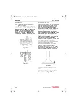
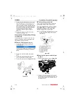
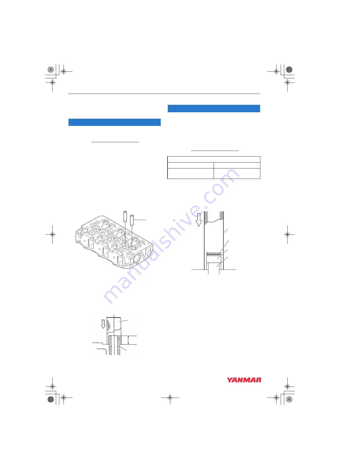
1. The valve guides are installed into the cylinder
head with an extremely tight press fit. Before
installing the valve guides, place the valve
guides in a freezer for at least twenty minutes
This will cause the valve guides to contract,
making it easier to install the valve guides into
place.
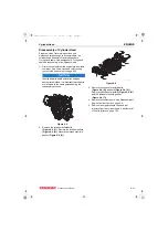
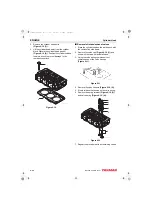
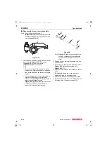
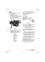
2. Immediately after removing the valve guides
from the freezer, insert the valve guides
in their proper positions.
Figure 6-27
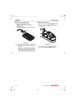
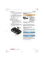
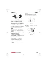
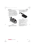
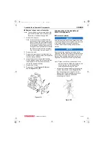
3. Finish installing the valve guides
into the cylinder head to the
proper height
using the valve
guide installation tool
(Figure 6-28, (2))
.
See
Valve Guide Projection specification starting on
page 6-4.
Figure 6-28
■
Reassembly of intake and exhaust valves
NOTICE
Always install new valve stem seals.
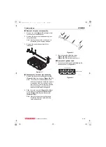
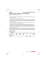
The exhaust valve stem seals are different than the
intake valve stem seals and can be identified by
either the paint marks on the outside of the seals or
by the color of the seal spring
.
Ensure they are installed in the correct locations.
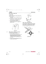
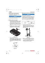
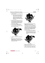
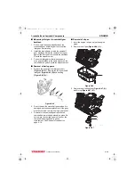
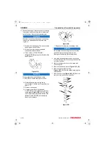
1. Oil the lip of the valve stem seal
(Figure 6-29, (2)).
Using the valve stem seal
installation tool
, install a new
valve stem seal on each of the valve guides
(Figure 6-29, (3))
.
Figure 6-29
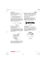
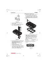
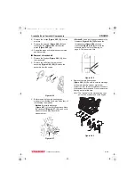
2. Measure the distance
(Figure 6-30, (1))
from
the cylinder head to valve stem seal to ensure
proper clearance
(Figure 6-30, (2))
between
the guide and the seal.
See Valve Stem Seal
Projection specification on page 6-5.
1
046619-00X00
K0001756A
3
2
1
Marking
Intake
Exhaust
None
Yellow
(Paint on outside of seal)
3
2
4
1
K0001873B
3TNV88F_SVM_A4.book 26 ページ 2012年7月26日 木曜日 午後6時4分

