


ENGINE
TNV DI Service Manual
6-43
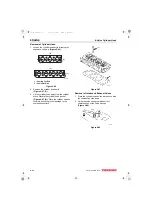
2-Valve Cylinder Head
Figure 6-22
Figure 6-23
Valve Face and Valve Seat
Always check the clearance between the valve and
valve guide before grinding or lapping the valve
seats. See Intake / Exhaust Valve and Guide on
page 6-7 for the service limit. If the clearance
exceeds the limit, replace the valve and / or valve
guide to bring the clearance within the limit.
Roughness or burrs will cause poor seating of a
valve. Visually inspect the seating surfaces of each
valve and valve seat to determine if lapping or
grinding is needed.
Visually inspect all valve faces and valve seats for
pitting, distortion, cracking, or evidence of
overheating. Usually the valves and the valve seats
can be lapped or ground to return them to
serviceable condition. Severely worn or damaged
components will require replacement.
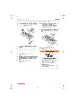
Coat the valve seat with a thin coat of bluing
compound. Install the valve and rotate it to
distribute bluing onto the valve face. The contact
pattern should be approximately centered on the
valve face (Figure 6-24, (1)) and even in width.
Figure 6-24
Also visually inspect the valve seat for even
contact.
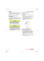
Light cutting can be performed by the use of a
hand-operated cutter (Figure 6-25, (3)).
Figure 6-25
The valve seat diameter can be adjusted by top-
grinding with a 150° stone to make the seat
diameter smaller, and bottom-grinding using a 40°
stone to make the seat diameter larger. Once the
seat location has been corrected, grind and lap the
seat angle (Figure 6-25, (1)) to specification. See
Cylinder Head on page 6-6 for specifications.
0000193
0001755
0001691B
(1)
0001862
(1)
40°
150°
(2)
(3)
TNV_DI_SM_A4.book 43 ページ 2007年12月6日 木曜日 午前9時23分


