FUEL SYSTEM
7-34
TNV DI Service Manual
Checking and Adjusting Fuel Injection Timing
13. If the injection timing is correct, remove the dial
indicator and adapter. Replace the pump
plunger plug and its copper gasket and tighten
to specifications. Replace the flywheel
inspection port cover. Open the fuel supply
valve and remove the clamp from the fuel
supply hose and the fuel return hose.
14. Prime the fuel system. Operate the engine and
check for leaks.
Adjusting Fuel Injection Timing
If the timing marks did not align when performing
the Checking Fuel Injection Timing on page 7-31,
the following steps must be performed to properly
time the engine.
1. Leave the dial indicator installed in the fuel
injection pump. Do not disturb the reading on
the dial indicator.
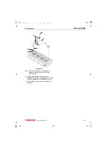
2. Rotate the flywheel until the target timing mark
(Figure 7-46, (1)) and the timing reference
mark (Figure 7-46, (2)) on the flywheel housing
or back plate are aligned.
IMPORTANT
Do not rotate the crankshaft during the
remainder of this procedure.
Figure 7-46
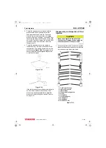
3. Note the reading on the dial indicator
(Figure 7-47, (1)). If the reading is less than
2.5 mm (0.098 in.), the fuel injection timing is
“retarded.” If the dial indicator reading is greater
than 2.5 mm (0.098 in.), the fuel injection timing
is “advanced.”
Figure 7-47
Note: Some model engines require the intake
manifold and fuel injection pump
insulator be removed to access the inner
fuel injection pump retaining nuts.
4. Loosen the nuts fastening the fuel injection
pump to the gear case or front plate. Loosen
the rear bracket(s) on the fuel injection pump.
Note: Loosening the high-pressure injection
line nuts on the fuel injection pump may
make rotating the pump easier.
5. Rotate the fuel injection pump until the dial
indicator reads 2.5 mm (0.098 in.).
6. To “advance” the injection timing, rotate the top
of the fuel injection pump away from the engine.
7. To “retard” the injection timing, rotate the top of
the fuel injection pump toward the engine.
8. When the dial indicator reads 2.5 mm
(0.098 in.) of pump plunger lift and the target
timing mark on the flywheel aligns with the
reference mark on the flywheel housing or
engine back plate, the injection timing is
correct.
0002066
(2)
(1)
0002069
(1)
TNV_DI_SM_A4.book 34 ページ 2007年12月6日 木曜日 午前9時23分
Содержание 3TNV82A-B
Страница 6: ...TABLE OF CONTENTS iv TNV DI Service Manual This Page Intentionally Left Blank TNV_DI_SM_A4 book iv...
Страница 8: ...INTRODUCTION 1 2 TNV DI Service Manual This Page Intentionally Left Blank TNV_DI_SM_A4 book 2...
Страница 10: ...YANMAR WARRANTIES 2 2 TNV DI Service Manual This Page Intentionally Left Blank TNV_DI_SM_A4 book 2...
Страница 18: ...SAFETY 3 2 TNV DI Service Manual This Page Intentionally Left Blank TNV_DI_SM_A4 book 2...
Страница 40: ...SAFETY 3 24 TNV DI Service Manual Safety Precautions This Page Intentionally Left Blank TNV_DI_SM_A4 book 24...
Страница 92: ...PERIODIC MAINTENANCE 5 2 TNV DI Service Manual This Page Intentionally Left Blank TNV_DI_SM_A4 book 2...
Страница 284: ...FUEL SYSTEM 7 44 TNV DI Service Manual Fuel Injectors This Page Intentionally Left Blank TNV_DI_SM_A4 book 44...
Страница 286: ...COOLING SYSTEM 8 2 TNV DI Service Manual This Page Intentionally Left Blank TNV_DI_SM_A4 book 2...
Страница 298: ...COOLING SYSTEM 8 14 TNV DI Service Manual Engine Coolant Pump This Page Intentionally Left Blank TNV_DI_SM_A4 book 14...
Страница 300: ...LUBRICATION SYSTEM 9 2 TNV DI Service Manual This Page Intentionally Left Blank TNV_DI_SM_A4 book 2...
Страница 318: ...LUBRICATION SYSTEM 9 20 TNV DI Service Manual Trochoid Oil Pump This Page Intentionally Left Blank TNV_DI_SM_A4 book 20...
Страница 320: ...TURBOCHARGER 10 2 TNV DI Service Manual This Page Intentionally Left Blank TNV_DI_SM_A4 book 2...
Страница 334: ...TURBOCHARGER 10 16 TNV DI Service Manual Periodic Inspection This Page Intentionally Left Blank TNV_DI_SM_A4 book 16...
Страница 336: ...STARTER MOTOR 11 2 TNV DI Service Manual This Page Intentionally Left Blank TNV_DI_SM_A4 book 2...
Страница 378: ...ELECTRONIC CONTROL SYSTEM 13 2 TNV DI Service Manual This Page Intentionally Left Blank TNV_DI_SM_A4 book 2...
Страница 383: ...ELECTRONIC CONTROL SYSTEM TNV DI Service Manual 13 7 Electronic control harness connections TNV_DI_SM_A4 book 7...
Страница 386: ...ELECTRIC WIRING 14 2 TNV DI Service Manual This Page Intentionally Left Blank TNV_DI_SM_A4 book 2...


