


FUEL SYSTEM
7-22
TNV IDI Service Manual
Fuel Injectors
Adjusting Fuel Injection Timing
If the timing marks did not align when performing
the
Checking Fuel Injection Timing on page 7-18
,
the following steps must be performed to properly
time the engine.
1. Leave the “spill-timing” tool installed in the fuel
injection pump.
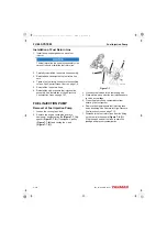
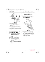
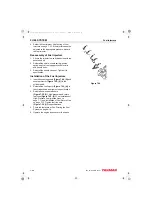
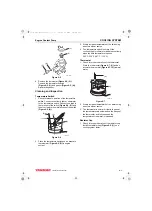
2. Determine if the timing is “advanced” or
“retarded” by comparing the position of the
target timing mark on the flywheel grid
(Figure 7-29, (1))
with the timing mark on the
flywheel housing or back plate
(Figure 7-29, (2))
.
Figure 7-29
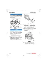
3. Loosen the nuts fastening the fuel injection
pump to the gear case.
4. If the injection timing was less than the target
timing, the injection timing is “retarded” and will
need to be “advanced.”
To “advance” the injection timing
: Rotate the
top of the fuel injection pump away from the
engine.
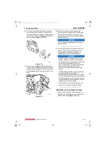
If the injection timing was greater than the target
timing, the injection timing is “advanced” and will
need to be “retarded.”
To “retard” the injection timing
: Rotate the top
of the fuel injection pump toward the engine.
5. Adjust the position of the fuel injection pump
and tighten the fuel injection pump mounting
nuts.
6. Recheck the fuel injection timing. Repeat the
fuel injection timing and adjustment procedures
until the timing is correct.
Injection Timing on page 7-18 and repeat steps
3 - 6.
7. Remove the “spill-timing” tool.
8. Reinstall the shut-off solenoid.
9. Reinstall the high-pressure fuel injection lines.
See Installation of High-Pressure Fuel Injection
Lines on page 7-11.
10. Replace the flywheel inspection port cover.
11. Prime the fuel system. Operate the engine and
check for leaks.
FUEL INJECTORS
Removal of Fuel Injectors
1. Close any fuel valves in the fuel supply line.
2. Clean the area around the fuel injection pump
and fuel injectors to keep contaminants from
entering the engine or fuel system.
3. Remove the high-pressure fuel injection lines
as an assembly.
Fuel Injection Lines on page 7-10.
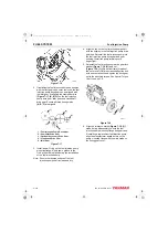
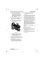
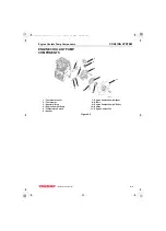
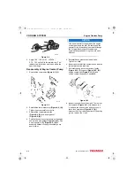
4. Remove nut
(Figure 7-30, (1))
. Remove the
fuel return line
(Figure 7-30, (2))
and copper
washer
(Figure 7-30, (3))
from the fuel
See Removal of Fuel Return Line on
Note: The fuel injectors used on IDI engines
screw into the cylinder head.
5. Remove the fuel injectors
(Figure 7-30, (4))
.
0002469
(2)
(1)
TNV_IDI_ServiceManual_A4.book 22 ページ 2012年2月24日 金曜日 午前10時24分