Yamazen AI-580S Скачать руководство пользователя страница 3

How to Replace the UV Lamp (A390)


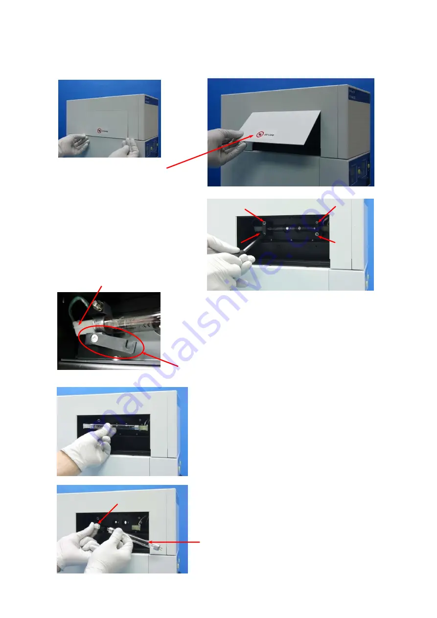
Remove  the  cover  (magnet) 
as shown in the photo. 

Install a new UV lamp. 


Loosen 4 screws, and trip the fixing bracket.   

Remove  the  connectors  at  both  ends  of 

the UV lamp, and take out the UV lamp. 


Connector 

A New UV lamp 


Fixing bracket 

Connector 

- 2 - 

Содержание AI-580S

Страница 1: ...ace Pump Head Module A217 A218 of AI 700X 3 4 How to Replace Pump Head A219 Piston Cylinder Group 5 How to Replace RH Assembly A219 P030 P044 6 7 How to Replace PC boards in fraction collector 8 How to Replace EEPROM 9 How to Replace Solenoid Valve A763 on Fraction Collector 10 How to Make Tubing with Fitting at its end 11 How to Make Flare Type Tubing 12 W Prep 2XY AI 580S AI 700X ...

Страница 2: ...s better To start prepare a container for waste then connect the tubing from pump column to the outlet tubing of the UV detector and let the inlet tubing of the UV detector work as the waste tubing Loosen the screw then pull the knob to remove the flow cell Tubing going to fraction collector Outlet Inlet Tubing coming from pump column Knob Screw 1 ...

Страница 3: ...move the cover magnet as shown in the photo Install a new UV lamp Loosen 4 screws and trip the fixing bracket Remove the connectors at both ends of the UV lamp and take out the UV lamp Connector A New UV lamp Fixing bracket Connector 2 ...

Страница 4: ...How to Replace Pump Head Module A217 A218 of AI 700X Step 1 Remove front cover by loosening 4 screws as shown by A Step 2 Loosen 2 fixing dials A A A A A Fixing Dials 3 ...

Страница 5: ...d module from the pivot When removing the pump head do not pull out the piston from cylinder more than 45mm Step 4 Install a new pump head module Step 5 Fix the pump head module by tightening the two dials MAX45mm Pivot Piston 4 ...

Страница 6: ...head A219 will appear Step 2 Do not pull out the piston more than 25mm from the cylinder Step 3 To install the pump head move the pivot hole inside to 2 o clock position with baby finger align the hook and put it into the pivot hole Put cylinder cap P030 on pump head A219 A Cylinder cap P030 Pivot Pump head A219 MAX25mm Pivot hole Hook 5 ...

Страница 7: ...lace RH Assembly A219 P030 P044 Step 1 Loosen screw A 2 ea and screw B 2 ea and remove the sheet metal Step 2 Remove 4 ea of screw C and pull out RH assembly Sheet metal has been removed A A B B C C RH Assembly 6 ...

Страница 8: ...Step 3 Install a new RH Assembly and fix it with 4 C screws Step 4 Put the sheet metal back on using A screws and B screws Holes for C screws Holes for C screws A A B B 7 ...

Страница 9: ...d Step 2 Pull out board Step 3 Insert a new board Step 4 Put screws back on the board bracket and tighten A880 Control board N022 A881 Interface board N020 Insert a new board on the guide slot at both sides Slot Screws A880 control board for Ch 1 A880 control board for Ch 2 A881 interface board 8 ...

Страница 10: ...EEPROM on the board in a right direction There is a half circle recession at one end of EEPROM and its socket The correct direction can be determined by this half circle recession Half circle recession Firmware Type Puller N260 137r DIP40P EXTRACTOR GX7 N360 137r DIP40P EXTRACTOR GX7 MX120 02 DIP20P EXTRACTOR GX3 MX520 01 DIP20P EXTRACTOR GX3 9 EXTRACTOR GX7 EXTRACTOR GX3 MX120 02 MX520 01 DIP20P ...

Страница 11: ...screws A on solenoid valve bracket Step 2 Loosen these 2 screws B and remove signal cable Step 3 Prepare a new solenoid valve Insert the signal cable and tighten 2 screws B Step 4 Fix the new solenoid to bracket by tightening two screws A A B A Signal cable 10 B Signal cable ...

Страница 12: ...e Tubing with Fitting at its end Fit Set B540 1 6mm O D B543 2mm O D B555 3mm O D B556 3mm O D B557 4mm O D Insert tubing all the way in to fitting Tighten female screw and male screw together to make fitting 11 ...

Страница 13: ...t Step 2 Heat the tubing end using a soldering bit Step 3 Push the tubing against flare fixture after it is heated well Step 5 Remove the flare fixture Flare tubing has been made Step 4 Screw the flare nut on to the flare fixture and wait until tubing is cooled down 12 ...

Страница 14: ... 6304 3681 R D SANWA BLDG 101 4 6 10 NISHINAKAJIMA YODOGAWA KU OSAKA 532 0011 JAPAN TEL 81 6 6304 7284 FAX 81 6 6304 7283 TOKYO OFFICE AKIMOTO BLDG 17 KANDATOMIYAMA CHIYODA KU TOKYO 101 0043 JAPAN TEL 81 3 5256 6481 FAX 81 3 5256 6480 E mail info yamazenc co jp WEB SITE www yamazenc co jp YAMAZEN CORPORATION January 2012 ...

Отзывы: