


4-74
CRANKCASE AND CRANKSHAFT
DISASSEMBLING THE CRANKCASE
1. Separate:
• Right crankcase
• Left crankcase
Separation steps:
a. Remove the crankcase bolts, hose guide
and clutch cable holder.
Loosen each bolt 1/4 of a turn at a time and af-
ter all the bolts are loosened, remove them.
b. Remove the right crankcase "1".
• Place the crankcase with its left side down-
ward and split it by inserting a screwdriver tip
into the splitting slit "a" in the crankcase.
• Lift the right crankcase horizontally while light-
ly patting the case splitting slit and engine
mounting boss using a soft hammer, and
leave the crankshaft and transmission with
the left crankcase.
Use soft hammer to tap on the case half.
Tap only on reinforced portions of case. Do
not tap on gasket mating surface. Work
slowly and carefully. Make sure the case
halves separate evenly. If the cases do not
separate, check for a remaining case bolt or
fitting. Do not force.
c. Remove the dowel pins and O-ring.
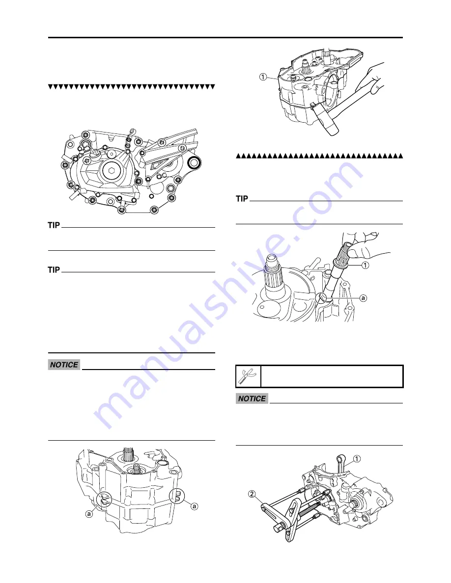
REMOVING THE BALANCER SHAFT
1. Remove:
• Balancer shaft "1"
Remove the balancer shaft with its flat side "a"
facing the crankshaft.
REMOVING THE CRANKSHAFT
1. Remove:
• Crankshaft "1"
Use the crankcase separating tool "2".
•Install the crankcase separating tool as
shown.
•Do not use a hammer to drive out the
crankshaft.
Crankcase separating tool:
YU-A9642/90890-04152
Содержание YZ450FA 2011
Страница 6: ...YAMAHA MOTOR CORPORATION U S A YZ MOTORCYCLE LIMITED WARRANTY ...
Страница 10: ...MEMO ...
Страница 57: ......
Страница 58: ...2 21 LUBRICATION DIAGRAMS LUBRICATION DIAGRAMS ...
Страница 60: ...2 23 CABLE ROUTING DIAGRAM CABLE ROUTING DIAGRAM ...
Страница 62: ...2 25 CABLE ROUTING DIAGRAM F F A B D D C C E F F C C D D B A E 100mm ...
Страница 64: ...2 27 CABLE ROUTING DIAGRAM B B F G A A C C D D E E B B G F C C D D E E A A ...
Страница 66: ...2 29 CABLE ROUTING DIAGRAM ...
Страница 68: ...2 31 CABLE ROUTING DIAGRAM ...
Страница 70: ...2 33 CABLE ROUTING DIAGRAM ...
Страница 90: ...3 19 ENGINE INTAKE EXHAUST ...
Страница 106: ...3 35 CHASSIS LUBRICATION ...
Страница 115: ...4 4 EXHAUST PIPE AND SILENCER 10 Exhaust pipe 1 1 11 Gasket 3 12 Heat protector 1 Order Part name Q ty Remarks ...
Страница 159: ...4 48 BALANCER 11 Balancer shaft driven gear 1 Order Part name Q ty Remarks ...
Страница 231: ...5 37 HANDLEBAR 14 Handlebar lower holder 2 15 Cap 1 Order Part name Q ty Remarks ...
Страница 249: ...5 55 REAR SHOCK ABSORBER 9 Bearing 2 Refer to removal section Order Part name Q ty Remarks ...
Страница 260: ...6 7 THROTTLE BODY DISASSEMBLING THE THROTTLE BODY Order Part name Q ty Remarks 1 Injector 1 2 Gasket 2 ...


