HANDLEBAR
4-10
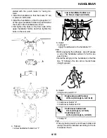
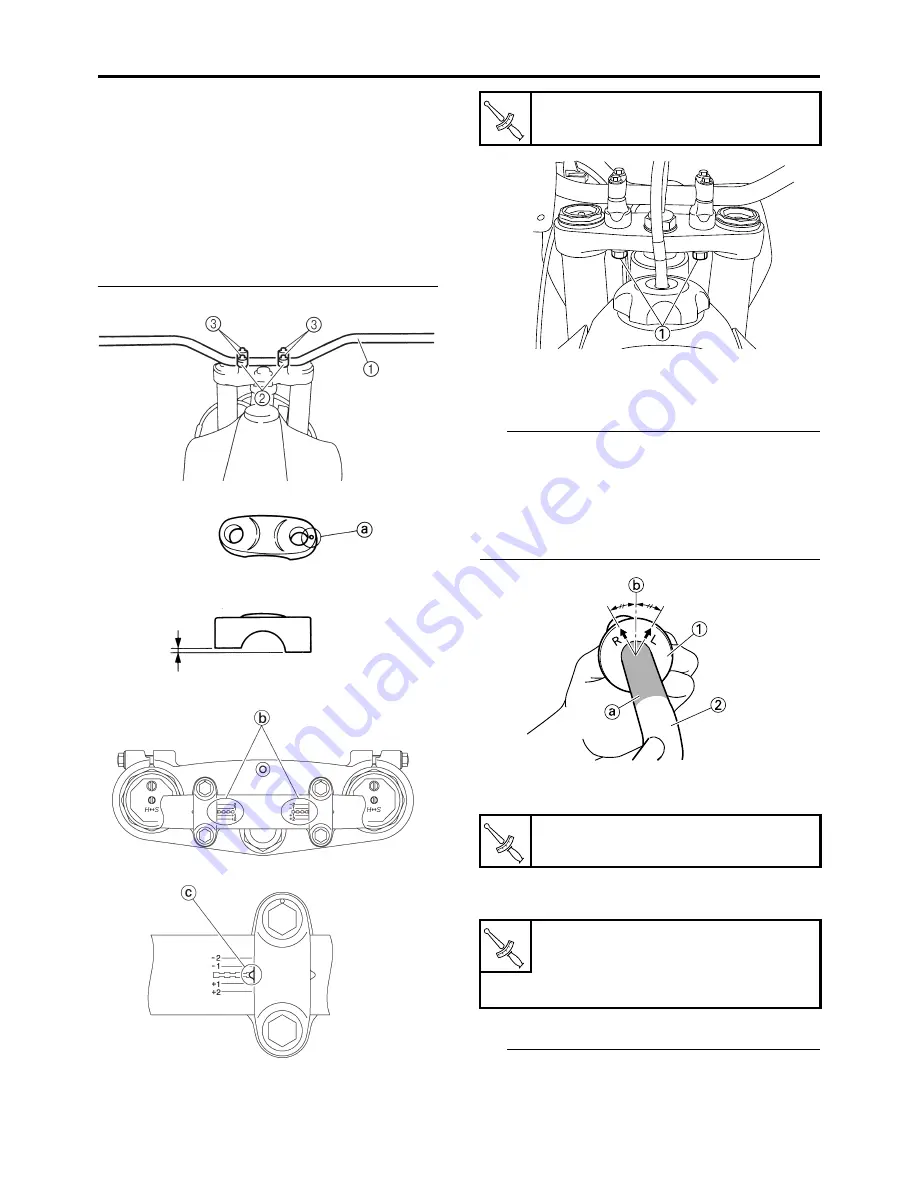
stalled with the punch marks “a” facing for-
ward.
•
Install the handlebar so that the marks “b” are
in place on both sides.
•
Install the handlebar so that the projection “c”
of the upper handlebar holders is positioned at
the mark on the handlebar as shown.
•
First tighten the bolts on the front side of the
upper handlebar holder, and then tighten the
bolts on the rear side.
4. Tighten:
•
Lower handlebar holder nut “1”
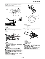
5. Install:
•
Left grip “1”
Apply the adhesive to the handlebar “2”.
TIP
•
Before applying the adhesive, wipe off grease
or oil on the handlebar surface “a” with a lac-
quer thinner.
•
Install the left grip to the handlebar so that the
line “b” between the two arrow marks faces
straight upward.
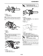
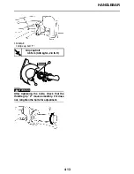
6. Install:
•
Engine stop switch “1”
•
Clutch lever holder “2”
•
Clutch lever holder bolt “3”
•
Clamp “4”
TIP
•
The engine stop switch, clutch lever holder and
clamp should be installed according to the di-
mensions shown.
Lower handlebar holder nut
40 N·m (4.0 kgf·m, 30 lb·ft)
Engine stop switch screw
0.5 N·m (0.05 kgf·m, 0.37 lb·ft)
Clutch lever holder bolt
5 N·m (0.5 kgf·m, 3.7 lb·ft)
Clutch lever nut
4.0 N·m (0.40 kgf·m, 3.0 lb·ft)
T
R
.
.
T
R
.
.
T
R
.
.
Содержание YZ250 2021
Страница 5: ...EAM20162 YAMAHA MOTOR CORPORATION U S A YZ MOTORCYCLE LIMITED WARRANTY ...
Страница 6: ......
Страница 8: ......
Страница 10: ...MOTORCYCLE CARE AND STORAGE 1 16 CARE 1 16 STORAGE 1 17 ...
Страница 42: ...TIGHTENING TORQUES 2 13 ...
Страница 70: ...CHASSIS 3 26 ...
Страница 106: ...CHAIN DRIVE 4 34 ...
Страница 112: ...CLUTCH 5 5 ...
Страница 113: ...1 2 3 4 5 6 7 8 9 10 ELECTRICAL SYSTEM WIRING DIAGRAM 6 1 COLOR CODE 6 1 ...
Страница 128: ...TROUBLESHOOTING 7 13 ...
Страница 146: ...CHASSIS 8 17 ...


