PERIODIC MAINTENANCE AND MINOR REPAIR
6-33
6
7. Lift the rear wheel off the ground
according to the procedure on
page 6-30.
8. While supporting the drive shaft,
pull the rear wheel back to remove
the following parts as an assem-
bly: wheel, wheel axle, final gear
case, and drive shaft.
NOTE:
Make sure to support the drive shaft as
it is being pulled out.
EAU25511
To install the rear wheel
1. Install the rear wheel, wheel axle,
final gear case, and drive shaft by
pushing the wheel forward and
guiding the drive shaft into the mid-
dle gear universal joint.
2. Install the final gear case bolts.
3. Install the brake rod onto the brake
camshaft lever, and then install the
brake pedal free play adjusting nut
onto the brake rod.
4. Install the brake torque rod bolt
and nut at the brake shoe plate.
5. Install the panel.
6. Lower the rear wheel so that it is
on the ground.
7. Tighten the axle nut, the final gear
case bolts and the brake torque
rod nuts to the specified torques.
8. Adjust the brake pedal free play.
(See page 6-18.)
WARNING
EWA10660
After adjusting the brake pedal free
play, check the operation of the
brake light.
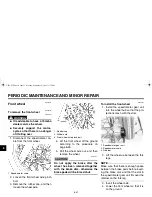
1. Bolt
2. Final gear case
1. Middle gear universal joint
2. Drive shaft
Tightening torques:
Axle nut:
92 Nm (9.2 m·kgf, 67 ft·lbf)
Final gear case bolt:
74 Nm (7.4 m·kgf, 54 ft·lbf)
Brake torque rod nut:
20 Nm (2.0 m·kgf, 14 ft·lbf)
U5SCE1E0.book Page 33 Monday, September 8, 2003 11:32 AM
Содержание XVS650A
Страница 1: ...5SC 28199 E1 XVS650A OWNER S MANUAL...
Страница 84: ...A5 yoko_Blank fm Page 1 Tuesday April 8 2003 11 43 AM...
Страница 85: ...A5 yoko_Blank fm Page 1 Tuesday April 8 2003 11 43 AM...
Страница 86: ...PRINTED ON RECYCLED PAPER YAMAHA MOTOR CO LTD PRINTED IN JAPAN 2003 09 0 3 1 CR E...


