3-25
CHASSIS
ADJUSTING THE REAR SHOCK
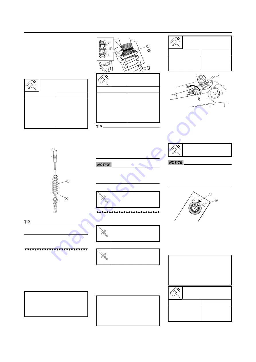
ABSORBER SPRING PRELOAD
1. Elevate the rear wheel by placing
the suitable stand under the en-
gine.
2. Remove:
• Rear frame
3. Measure:
• Spring fitting length
The I.D. mark "a" is marked at the end
of the spring.
4. Adjust:
• Spring preload
Adjustment steps:
a. Loosen the locknut "1".
b. Loosen the adjuster "2" until there
is some clearance between the
spring and adjuster.
c. Measure the spring free length
"a".
d. Turn the adjuster "2".
• Be sure to remove all dirt and mud
from around the locknut and adjust-
er before adjustment.
• The length of the spring (installed)
changes 1.5 mm (0.06 in) per turn
of the adjuster.
Never attempt to turn the adjuster
beyond the maximum or minimum
setting.
e. Tighten the locknut.
5. Install:
• Rear frame (upper)
• Rear frame (lower)
ADJUSTING THE REAR SHOCK
ABSORBER REBOUND DAMPING
FORCE
1. Adjust:
• Rebound damping force
By turning the adjuster "1".
• STANDARD POSITION:
This is the position which is back
by the specific number of clicks
from the fully turned-in position.
(Which align the punch mark "a"
on the adjuster with the punch
mark "b" on the bracket.)
Do not force the adjuster past the
minimum or maximum extent of
adjustment. The adjuster may be
damaged.
ADJUSTING THE REAR SHOCK
ABSORBER LOW COMPRESSION
DAMPING FORCE
1. Adjust:
• Low compression damping force
By turning the adjuster "1".
Standard fitting length:
I.D. MARK/Q'TY
Length
Yellow/1
249 mm
(9.80 in)
* 245.0 mm
(9.65 in)
** 248.5 mm
(9.78 in)
* For AUS, NZ and ZA
** For EUROPE
Stiffer
→
Increase the spring pre-
load. (Turn the adjuster "2" in.)
Softer
→
Decrease the spring pre-
load. (Turn the adjuster "2"
out.)
Extent of adjustment:
Maximum
Minimum
Position in
which the
spring is turned
in 13 mm (0.51
in) from its free
length.
Position in
which the
spring is turned
in 1.5 mm (0.06
in) from its free
length.
Locknut:
30 Nm (3.0 m•kg, 22
ft•lb)
Rear frame (upper):
38 Nm (3.8 m•kg, 27
ft•lb)
Rear frame (lower):
32 Nm (3.2 m•kg, 23
ft•lb)
Stiffer "a"
→
Increase the re-
bound damping force. (Turn
the adjuster "1" in.)
Softer "b"
→
Decrease the re-
bound damping force. (Turn
the adjuster "1" out.)
Extent of adjustment:
Maximum
Minimum
Fully turned in
position
20 clicks out
(from maximum
position)
Standard position:
About 11 clicks out
Stiffer "a"
→
Increase the low
compression damping force.
(Turn the adjuster "1" in.)
Softer "b"
→
Decrease the low
compression damping force.
(Turn the adjuster "1" out.)
Extent of adjustment:
Maximum
Minimum
Fully turned in
position
20 clicks out
(from maximum
position)
Содержание WR250F(Y) 2009
Страница 2: ......
Страница 43: ......
Страница 45: ...2 19 LUBRICATION DIAGRAMS 1 Crankshaft 2 Oil filter element 3 Oil tank 4 Oil hose A From oil pump...
Страница 71: ...3 18 ENGINE INTAKE EXHAUST...
Страница 84: ...3 31 ELECTRICAL Charging method using a variable voltage charger...
Страница 85: ...3 32 ELECTRICAL Charging method using a constant voltage charger...
Страница 223: ......
Страница 224: ...PRINTED IN JAPAN E PRINTED ON RECYCLED PAPER YAMAHA MOTOR CO LTD 2500 SHINGAI IWATA SHIZUOKA JAPAN...


