background image


*LIT186660028*


ASSEMBLY MANUAL


LIT-18666-00-28

F0X-28107-ZA-11


WaveRunnerGP1200R

Содержание WaveRunner GP1200R

Страница 1: ... LIT186660028 ASSEMBLY MANUAL LIT 18666 00 28 F0X 28107 ZA 11 WaveRunnerGP1200R ...

Страница 2: ...EMBLY MANUAL 2000 Yamaha Motor Co Ltd 1st Edition January 2000 All rights reserved Any reprinting or unauthorized use without the written permission of Yamaha Motor Co Ltd is expressly prohibited Printed in USA LIT 18666 00 28 ...

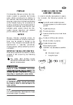
Страница 3: ...y important information is distin guished in this manual by the following notations The safety Alert Symbol means ATTENTION BECOME ALERT YOUR SAFETY IS INVOLVED WARNING Failure to follow WARNING instructions could result in severe injury or death to the machine operator a bystander or a person inspecting or repairing the water vehicle CAUTION A CAUTION indicates special precautions that must be ta...

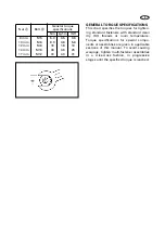
Страница 4: ...special compo nents or assemblies are given in applicable sections of this manual To avoid causing warpage tighten multi fastener assemblies in a criss cross fashion in progressive stages until the specified torque is reached Nut A Bolt B General torque specifications Nm kgf m lb ft 8 mm M5 5 0 0 5 3 6 10 mm M6 8 0 0 8 5 8 12 mm M8 18 1 8 13 14 mm M10 36 3 6 25 17 mm M12 43 4 3 31 ...

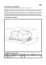
Страница 5: ...d during uncrating refer to the Yamaha Warranty Handbook Chapter 3 Documentation may be required for warranty reimbursement Do not continue with uncrating or throw the crate away until the requirements in Chapter 3 have been met COMPARTMENT DIAGRAM COMPARTMENT PART CHART No Part name Q ty Remarks 1 Water vehicle body 1 2 Carton box 1 ...

Страница 6: ...ube 1 90448 25800 8 Handlebar cover stay 1 GP7 U142K 00 9 Screw 6 15 mm 0 24 0 59 in 4 90159 069U1 10 Handlebar cover 1 GP7 U142A 11 11 Screw 6 19 mm 0 24 0 75 in 4 90149 069U9 12 Band 1 90601 200U2 13 Flashing conduction fitting 1 67X 12590 00 14 Tool kit 1 EU0 65986 00 15 Vinyl bag 1 EU0 65901 01 16 Spark plug 3 94702 00396 17 Owner s Operator s manual 1 F0X F8199 10 18 Riding practice tips 1 F0...

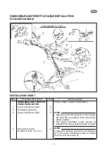
Страница 7: ...ints WIRE LEAD AND CABLE ROUTING Follow Step order for installation NOTE Working from the bow side open the front hood and then remove the storage com partment 1 Choke cable 1 2 Throttle cable 1 3 Handlebar switch lead 1 4 Grommet 1 NOTE Apply soapy water to the grommet for eas ier installation 5 QSTS cable 2 ...

Страница 8: ...r handlebar holder 2 2 Handlebar assembly 1 3 Upper handlebar holder 2 NOTE Align the punched marks a on the handle bar with the top surface of the lower han dlebar holders The upper handlebar holder should be installed with the punched mark b forward 4 Bolt with washer 8 55 mm 0 31 2 17 in 4 NOTE Tighten the bolts so that the front clearance c of the upper handlebar holder is smaller than the rea...

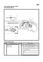
Страница 9: ...n steps Install the throttle cable end into the throttle lever Fit the seal into the groove in the bracket Turn the adjuster 1 in out until the specified free play is obtained Throttle lever free play e 4 7 mm 0 16 0 28 in Turn in Free play is increased Turn out Free play is decreased Tighten the locknut 2 ...

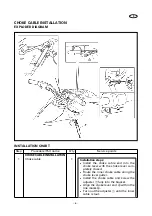
Страница 10: ...ble 1 Installation steps Install the choke cable end into the choke lever with the choke lever com pletely closed Route the inner choke cable along the choke lever gutter Install the choke cable and screw the adjuster 1 fully into the bracket Align the choke lever end a within the line marks b Turn out the adjuster 1 until the inner cable is taut ...

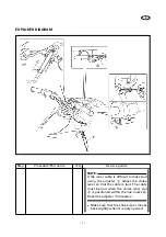
Страница 11: ... is difficult to make taut using the adjuster 1 adjust the choke lever so that the cable is taut The cable must be taut when the choke lever end a is positioned within the line marks b Reset the adjuster if necessary Make sure that the choke lever moves back slightly when it is fully opened ...

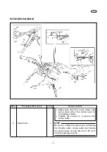
Страница 12: ...Be sure to install the spiral tube containing the throttle cable choke cable and handle bar switch lead at least 50 mm 1 97 in c into the steering column Make sure that the inner cable has some slack when the choke lever is completely closed Tighten the locknut 2 to secure the choke cable ...

Страница 13: ...HANDLEBAR COVER INSTALLATION Follow Step order for installation 1 Handlebar cover stay 1 2 Screw 6 15 mm 0 24 0 59 in 4 3 Handlebar cover 1 4 Screw 6 19 mm 0 24 0 75 in 4 NOTE If the handlebar cover is in contact with the steering console cover adjust the handlebar mount angle so that the clearance a and b are equal ...

Страница 14: ...DED DIAGRAM INSTALLATION CHART Step Procedure Part name Q ty Service points WIRING CONNECTION INSTALLATION Follow Step order for installation 1 Handlebar switch coupler 3 Black coupler 2 pins natural coupler 2 pins white coupler 1 pin 2 Band 1 ...

Страница 15: ... INSTALLATION Follow Step order for installation 1 QSTS cable 1 1 NOTE Set the inner cables length a to 77 mm 3 03 in using the adjusting nuts 1 when the control grip is in neutral before install ing the QSTS cables Tighten the locknuts 2 to secure the QSTS cables QSTS cable 2 is marked with white tape b 2 QSTS cable 2 1 ...

Страница 16: ...eather hose 1 NOTE Remove the fire extinguisher container for easier removing and installing the battery Charge the battery before installing it Refer to PREDELIVERY CHECK CAUTION Make sure that the battery breather hose is not pinched 2 Battery 1 3 Battery positive lead red 1 4 Bolt 6 12 mm 0 24 0 47 in 1 5 Battery negative lead black 1 6 Bolt 6 12 mm 0 24 0 47 in 1 7 Band 1 ...

Страница 17: ...rge quantities of water or milk Follow with milk of magnesia beaten egg or vegetable oil Call a physi cian immediately Eyes Flush with water for 15 minutes and get prompt medical attention Batteries produce explosive gases Keep sparks flame cigarettes etc away Ventilate when charging or using in an enclosed space Always shield your eyes when working near batteries KEEP OUT OF REACH OF CHILDREN CAU...

Страница 18: ...r to installation Filling steps Remove all the filler caps using pliers Fill with the specified electrolyte from a jug After the electrolyte is filled up as far as the UPPER LEVEL a allow the cell to stand for 20 minutes If after 20 min utes the electrolyte level has dropped add more electrolyte up to the UPPER LEVEL mark once again Specific gravity at 20 C 68 F 1 28 Charging current 68 4 kC 1 9 A...

Страница 19: ...ly YAMALUBE 2 W oil Using another oil can seriously damage the cat alytic converter and other engine compo nents Air bleeding steps Place rags around the air bleed screw 1 to catch any oil that might spill Fill the oil tank with the recommended engine oil Recommended engine oil YAMALUBE 2 W oil only Loosen the air bleed screw 1 two full turns and make sure that both the oil and air bubbles flow ou...

Страница 20: ...it to warm up for a few minutes Attach an engine tachometer to the spark plug lead Engine tachometer YU 8036 A 90890 06760 Measure the engine trolling speed 2 Adjust Trolling speed Adjustment steps Start the engine Turn the remote throttle stop screw 1 in or out until the specified speed is obtained Turn in Increase trolling speed Turn out Decrease trolling speed ...

Страница 21: ...pecification adjust the cable joint 2 Adjust Steering cable joint handle side Adjustment steps Loosen the locknut 1 Disconnect the cable joint 2 from the ball joint 3 Turn the cable joint in or out for adjusting the distances a and b Turn in Distance a is increased Turn out Distance b is increased WARNING The cable joint must be screwed in more than 8 mm 0 31 in Connect the cable joint and tighten...

Страница 22: ...ngth a and b If a and b length are not even adjust the cable joint Adjustment steps Set the control grip in the neutral posi tion Loosen the locknut 1 Remove the nut 2 and pivot pin 3 Set the jet nozzle in the center posi tion Turn the cable joint 4 in or out for adjusting length a and b Turn in Length b is increased Turn out Length a is increased WARNING The cable joint must be screwed in more th...

Страница 23: ...nly YAMALUBE 2 W oil Using another oil can seriously damage the catalytic converter and other engine components Item Unit GP1200R Trolling speed r min 1 350 50 Spark plug Type BR8ES 11 Gap mm in 1 0 1 1 0 039 0 043 Fuel and oil Fuel Regular unleaded gasoline with a minimum octane rating of 86 PON 1 or 91 RON 2 Engine oil YAMALUBE 2 W 3 Fuel tank capacity L US gal Imp gal 60 15 9 13 2 Oil tank capa...

Страница 24: ...Printed on recycled paper Printed in USA Jan 2000 0 0 1 CR F0X 28107 ZA 11 GP1200AY YAMAHA MOTOR CO LTD ...

Отзывы: