


8-14
E
HULL
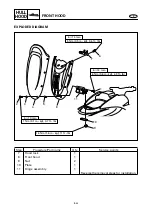
HOOD
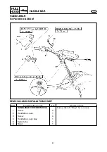
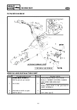
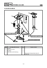
STEERING COLUMN
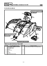
EXPLODED DIAGRAM
REMOVAL AND INSTALLATION CHART
*: Be sure to install the same number of shim(s) as installed originally at factory.
Step
Procedure/Part name
Q’ty
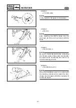
Service points
STEERING COLUMN
DISASSEMBLY
Follow the left “Step” for disassembly.
1
Grommet
1
2
Bolt/washer/nut
1/2/1
3
Steering arm
1
4
Shim
*
8
×
60 mm
16 Nm (1.6 m
•
kgf, 11 ft
•
Ib)
5 Nm (0.5 m
•
kgf, 3.6 ft
•
Ib)
26 Nm (2.6 m
•
kgf, 19 ft
•
Ib)
2
7
5
4
3
2
1
8
6
7
Содержание WaveRunner GP1200R
Страница 1: ...LIT186160215 SERVICE MANUAL LIT 18616 02 15 F0X 28197 ZA 11 WaveRunnerGP1200R...
Страница 86: ...5 7 POWR E MUFFLER ASSEMBLY SERVICE POINT Catalyst inspection 1 Inspect Catalyst Cracks damage Replace...
Страница 227: ...8 35 E HULL HOOD SEATS AND HAND GRIP SERVICE POINTS Seat lock inspection 1 Inspect Seat lock Damage wear Replace...
Страница 241: ...E 9 TRBL ANLS CHAPTER 9 TROUBLE ANALYSIS TROUBLE ANALYSIS 9 1 TROUBLE ANALYSIS CHART 9 1...
Страница 244: ...Printed on recycled paper Printed in USA Feb 2000 1 CR F0X 28197 ZA 11 GP1200AY YAMAHA MOTOR CO LTD...


