


FI
7-9
TROUBLESHOOTING CHART
Engine operation is not normal or the warning light and self-diagnostic warning indicator on the LCD flash.
* The warning light and self-diagnostic warning indicator on the upper LCD may not flash even if the engine
operation is not normal.
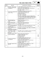
The warning light and self-diagnostic warning indi-
cator on the upper LCD flash.
Check the fault code number displayed on the me-
ter.
Identify the system with the malfunction. (Refer to
“Self-Diagnostic-Function table”.)
Identify the probable cause of the malfunction.
(Refer to “Fault code table”.)
Check and repair the probable cause of the mal-
function.
Fault code No.
No fault code No.
Check and repair.
(Refer to “TROUBLE-
SHOOTING
DETAILS”.)
Monitor the operation
of the sensors and ac-
tuators in the diagnos-
tic mode. (Refer to
“Diagnostic mode ta-
ble”.)
Check and repair.
Perform the fuel injection system reinstatement
action. (Refer to “Reinstatement method” in
“TROUBLESHOOTING DETAILS”.)
Turn the main switch off, turn the main switch
back on, and then check if the fault code number
is still displayed.
Fault code number not displayed
Repairs completed
Erasing the malfunction history:*
The malfunction history is stored even if the main switch is turned off.
The malfunction history must be erased in the diagnostic mode. (Refer to the “Diagnostic mode table (Di-
agnostic code No. 62)”.)
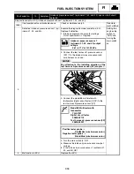
The warning light and self-diagnostic warning indi-
cator on the upper LCD does not flash.
Check the operation of the following sensors and
actuators in the diagnostic mode. (Refer to “Diag-
nostic mode table”.)
d:01:Throttle position sensor (throttle angle)
d:03, d:04:Intake air pressure
d:05:Intake air temperature
d:06:Coolant temperature
d:07:Snowmobile speed pulse
d:09:Fuel system voltage (battery voltage)
d:30:Cylinder-#1 ignition coil
d:31:Cylinder-#2 ignition coil
d:32:Cylinder-#3 ignition coil
d:36:Injector #1
d:37:Injector #2
d:38:Injector #3
Engine malfunction
OK
NG
Defective sensor or
actuator
Check and repair the
corresponding sen-
sor or actuator.
Check and repair
the inner parts of the
engine. (Refer to
CHAPTER 5.)
OK
NG
OK
Check the engine condition.
OK
Fault code number
displayed
* Operated when the warning light and self-diagnosis warning indicator flash.
FUEL INJECTION SYSTEM
Содержание Vector RS90GTZ
Страница 1: ......
Страница 74: ...INSP ADJ 2 51 Rear RST90GTZ Nipple Nipple both sides LUBRICATION ...
Страница 329: ...FI 7 2 Passenger grip warmer relay RS90GTZ RS90LTGTZ RST90GTZ FUEL INJECTION SYSTEM ...
Страница 330: ...FI 7 3 CIRCUIT DIAGRAM RS90GTZ RS90LTGTZ FUEL INJECTION SYSTEM ...
Страница 332: ...FI 7 5 CIRCUIT DIAGRAM RST90GTZ FUEL INJECTION SYSTEM ...
Страница 368: ...ELEC 8 2 IGNITION SYSTEM CIRCUIT DIAGRAM RS90GTZ RS90LTGTZ IGNITION SYSTEM ...
Страница 370: ...ELEC 8 4 CIRCUIT DIAGRAM RST90GTZ IGNITION SYSTEM ...
Страница 389: ...ELEC 8 23 CIRCUIT DIAGRAM RST90GTZ AC magneto Rectifier regulator Main fuse Battery Frame ground CHARGING SYSTEM ...
Страница 393: ...ELEC 8 27 CHARGING SYSTEM ...
Страница 394: ...ELEC 8 28 LIGHTING SYSTEM CIRCUIT DIAGRAM RS90GTZ RS90LTGTZ LIGHTING SYSTEM ...
Страница 396: ...ELEC 8 30 CIRCUIT DIAGRAM RST90GTZ LIGHTING SYSTEM ...
Страница 404: ...ELEC 8 38 SIGNAL SYSTEM CIRCUIT DIAGRAM RS90GTZ RS90LTGTZ SIGNAL SYSTEM ...
Страница 406: ...ELEC 8 40 CIRCUIT DIAGRAM RST90GTZ SIGNAL SYSTEM ...
Страница 419: ...ELEC 8 53 SIGNAL SYSTEM ...
Страница 420: ...ELEC 8 54 GRIP WARMER SYSTEM CIRCUIT DIAGRAM RS90GTZ RS90LTGTZ GRIP WARMER SYSTEM ...
Страница 422: ...ELEC 8 56 CIRCUIT DIAGRAM RST90GTZ GRIP WARMER SYSTEM ...
Страница 430: ...ELEC 8 64 COOLING SYSTEM CIRCUIT DIAGRAM RS90GTZ RS90LTGTZ COOLING SYSTEM ...
Страница 458: ...SPEC 9 25 CABLE ROUTING CABLE ROUTING ...
Страница 460: ...SPEC 9 27 CABLE ROUTING ...
Страница 462: ...SPEC 9 29 RS90GTZ RS90LTGTZ CABLE ROUTING ...
Страница 464: ...SPEC 9 31 RS90GTZ RS90LTGTZ CABLE ROUTING ...
Страница 466: ...SPEC 9 33 RST90GTZ CABLE ROUTING ...
Страница 468: ...SPEC 9 35 RST90GTZ CABLE ROUTING ...
Страница 470: ...SPEC 9 37 RST90GTZ CABLE ROUTING ...
Страница 472: ...SPEC 9 39 RS90GTZ RS90LTGTZ CABLE ROUTING ...
Страница 474: ...SPEC 9 41 RS90GTZ RS90LTGTZ CABLE ROUTING ...
Страница 476: ...SPEC 9 43 RST90GTZ CABLE ROUTING ...
Страница 478: ...SPEC 9 45 RST90GTZ CABLE ROUTING ...
Страница 480: ...SPEC 9 47 CABLE ROUTING ...
Страница 482: ...SPEC 9 49 CABLE ROUTING ...
Страница 484: ...SPEC 9 51 RS90GTZ RS90LTGTZ CABLE ROUTING ...
Страница 486: ...SPEC 9 53 RST90GTZ CABLE ROUTING ...
Страница 488: ...SPEC 9 55 RS90GTZ RS90LTGTZ CABLE ROUTING ...
Страница 490: ...SPEC 9 57 RST90GTZ CABLE ROUTING ...
Страница 492: ...SPEC 9 59 RST90GTZ CABLE ROUTING ...
Страница 498: ......
Страница 499: ......
Страница 500: ......
Страница 501: ...WIRING DIAGRAM 2010 RS90GTZ RS90LTGTZ 8JA 0F001 00 ...
Страница 502: ...WIRING DIAGRAM 2010 RST90GTZ 8HF 0F001 00 ...
Страница 503: ...WIRING DIAGRAM 2010 RS90GTZ RS90LTGTZ 8JA 0F001 00 ...
Страница 504: ...WIRING DIAGRAM 2010 RST90GTZ 8HF 0F001 00 ...


