


2-1
Outboard Rigging Guide - 2001
Engine Mounting Dimensions
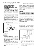
ENGINE MOUNTING DIMENSIONS
(TRANSOM ONLY)
Proper mounting of the outboard will mean better
performance, maximum reliability, and maximum
customer satisfaction. This chapter contains the
specifications necessary for motor mounting.
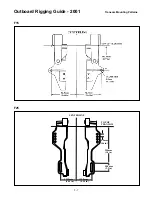
For correct mounting, the cavitation plate should
be equal to the bottom of the transom, or 25mm+
(1.0 inch). If higher mounting is used for perfor-
mance applications, it is recommended that a
water pressure gauge be installed so pressure can
be monitored.
When mounting, also make sure the motor has the
clearance to provide full movement, from both
port to starboard, as well as during trim/tilt func-
tions.
NOTE: For bracket application -
Refer to bracket manufacturer for installation
specifications.
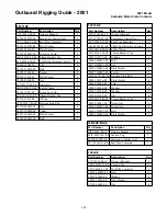
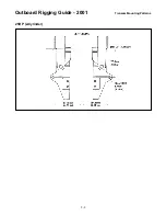
Transom Dimensions
A
=
Steering Rotation (each way, from cen–
terline)
B
=
Maximum tilt angle (including 12° tran–
som angle)
C
=
Protrusion into boat at maximum tilt
D
=
Cavitation plate distance from top of
transom
E
=
Steering clearance (each way, from cen–
terline)
F
=
Powerhead clearance at rear of motor
(each way, from centerline)
G
=
Transom thickness (minimum - maxi
mum)
H
=
Transom bracket height
I
=
Chart
J
=
Maximum engine depth from top of
transom (0° trim)
K
=
Powerhead height
L
=
Maximum height at full tilt (powerhead)
M
=
Protrusion into boat (tiller handle mod–
els)
N
=
Maximum rearward protrusion of power
head from transom
0
=
Protrusion into boat (remote models)
P
=
Maximum rearward protrusion of lower
unit from transom (@ level trim)
Q
=
Distance, propeller shaft from cavitation
plate
R
=
Minimum twin-engine center-to-center
distance
J+K =
Overall height
M+N=
Overall depth (tiller models)
N+O =
Overall depth (remote models)
Bolt Pattern: Bolt patterns are on the following
pages.
Содержание T8
Страница 2: ......
Страница 9: ......
Страница 35: ......
Страница 37: ......
Страница 61: ......
Страница 63: ......
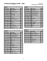
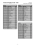
Страница 65: ...2 2 Outboard Rigging Guide 2001 Engine Mounting Dimensions...
Страница 67: ...2 4 Outboard Rigging Guide 2001 Engine Mounting Dimensions...
Страница 69: ...2 6 Outboard Rigging Guide 2001 Transom Mounting Patterns TRANSOM MOUNTING PATTERNS F9 9 T9 9 9 9HP 15HP...
Страница 71: ...2 8 Outboard Rigging Guide 2001 Transom Mounting Patterns 25HP 2 Cylinder...
Страница 72: ...2 9 Outboard Rigging Guide 2001 Transom Mounting Patterns 25X3 3 Cyl 30HP 40HP Manual Tilt...
Страница 109: ......
Страница 111: ......
Страница 128: ...3 17 Outboard Rigging Guide 2001 Switch Panels Oil Lamp Panel Assembly T9 9ELR 6G8 83530 00 00...
Страница 155: ...3 44 Outboard Rigging Guide 2001 Boat Wiring Diagrams T9 9 with 703 Control...
Страница 156: ...3 45 Outboard Rigging Guide 2001 T9 9 with Switch Panel...
Страница 157: ...3 46 Outboard Rigging Guide 2001 Boat Wiring Diagrams 9 9 30HP 30 C40 98 with 703 Control 10 pin and Analog Tachometer...
Страница 158: ...3 47 Outboard Rigging Guide 2001 Boat Wiring Diagrams 9 9 30HP 30 C40 98 with 10 pin Switch Panel and Analog Tachometer...
Страница 159: ...3 48 Outboard Rigging Guide 2001 Boat Wiring Diagrams Wiring 9 9 30HP with 7 Pin Harness Switch Panel...
Страница 160: ...3 49 Outboard Rigging Guide 2001 Boat Wiring Diagrams 40E 50HP with 703 Control Analog Tachometer Except 40T or P50...
Страница 161: ...3 50 Outboard Rigging Guide 2001 Boat Wiring Diagrams 40E 50HP with Switch Panel Analog Tachometer Except 40T or P50...
Страница 163: ...3 52 Outboard Rigging Guide 2001 Boat Wiring Diagrams F40 F50 T50 F80 100 F115 with Switch Panel and Analog Tachometer...
Страница 164: ...3 53 Outboard Rigging Guide 2001 Boat Wiring Diagrams C40 C150 with 703 Control and Analog Tachometer...
Страница 165: ...3 54 Outboard Rigging Guide 2001 Boat Wiring Diagrams C40 C150 with Switch Panel and Analog Tachometer...
Страница 168: ...3 57 Outboard Rigging Guide 2001 Boat Wiring Diagrams 115HP 250HP Wiring with 703 Control and Analog Gauges...
Страница 169: ...3 58 Outboard Rigging Guide 2001 Boat Wiring Diagrams 115HP 250HP Wiring with Switch Panel and Analog Gauges...
Страница 176: ...3 65 Outboard Rigging Guide 2001 Boat Wiring Diagrams F40 F50TLH T50 F80 F100 Tiller Model Analog Tachometer UNUSED...
Страница 177: ...3 66 Outboard Rigging Guide 2001 After Market Dash Wiring...
Страница 178: ...3 67 Outboard Rigging Guide 2001 COMPLETE BOAT WIRING DIAGRAMS 70 90HP F80 F115...
Страница 179: ...3 68 Outboard Rigging Guide 2001 Complete Boat Wiring Diagrams V4 V6 Single Engine...
Страница 180: ...3 69 Outboard Rigging Guide 2001 Complete Boat Wiring Diagrams V4 V6 Single Engine Cont d...
Страница 181: ...3 70 Outboard Rigging Guide 2001 Complete Boat Wiring Diagrams V4 V6 F115 Dual Engine...
Страница 182: ...3 71 Outboard Rigging Guide 2001 Complete Boat Wiring Diagrams V4 V6 F115 Dual Engine Cont d...
Страница 183: ...3 72 Outboard Rigging Guide 2001 Complete Boat Wiring Diagrams V6 HPDI Single Engine...
Страница 184: ...3 73 Outboard Rigging Guide 2001 Complete Boat Wiring Diagrams V6 HPDI Dual Engine...
Страница 185: ......
Страница 187: ......
Страница 236: ......
Страница 242: ...5 5 Outboard Rigging Guide 2001 Tachometer Digital Multi function Tachometer...
Страница 311: ...6 31 Outboard Rigging Guide 2001 F40 4 Cyl F T50 Tiller Handle Kit F40 4 Cyl F T50 TILLER HANDLE KIT 62Y W0086 Z0 4D...
Страница 336: ...6A 1 Outboard Rigging Guide 2001 Outboards F30 F40 TILLER HANDLE STEERING FRICTION INSTALLATION MANUAL...
Страница 347: ...6B 1 Outboard Rigging Guide 2001 Outboards F80 F100 TILLER HANDLE STEERING FRICTION INSTALLATION MANUAL 67G 2819K 10...
Страница 358: ...6C 1 Outboard Rigging Guide 2001 Outboards F80 F100 TILLER HANDLE STEERING FRICTION OWNER S MANUAL...
Страница 359: ...6C 2 Outboard Rigging Guide 2001 E FEATURES...
Страница 376: ...7 15 Outboard Rigging Guide 2001 F15 F25 Remote Control Attach Kit REMOVAL...
Страница 397: ...Outboard Rigging Guide 2001 SECTION 8 PROPELLERS Propellers 8 1 Propeller Application Charts 8 3 8...
Страница 406: ...NOTES...
Страница 407: ...NOTES...
Страница 418: ...Outboards 6X1 DUAL STATION SYSTEM INSTALLATION MANUAL YAMAHA MOTOR CO LTD 6X1 28199 Y2 10A 1...
Страница 423: ...10A 6 GENERAL INFORMATION WIRING AND COMPONENT PARTS Single engine system Second station...
Страница 424: ...10A 7 Twin engine system Second station...
Страница 451: ...After all the installation is completed check that the cables are properly connected as shown below 10A 34...
Страница 453: ...WIRING DIAGRAM FIRST STATION Single engine 10A 36...
Страница 454: ...SECOND STATION Single engine 10A 37...
Страница 455: ...10A 38...
Страница 456: ...10A 39...
Страница 457: ...Outboards 6X1 DUAL STATION SYSTEM SERVICE GUIDE 10B 1...
Страница 460: ...10B 4...
Страница 462: ...10B 6 Outboard Rigging Guide 2001 EXTERNAL VIEW OUTLINE OF FEATURES...
Страница 482: ...10B 26 Outboard Rigging Guide 2001 2 Arranging the remote control cables wire harnesses and steering cables...
Страница 495: ...10B 39 Outboard Rigging Guide 2001...
Страница 496: ...10B 40 Outboard Rigging Guide 2001...


