For Service Engineer
Service Information
SI1705004E-00=SIGMA-G5SII Service Manual
127/273
(3)
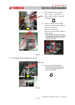
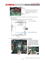
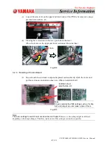
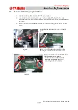
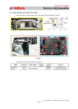
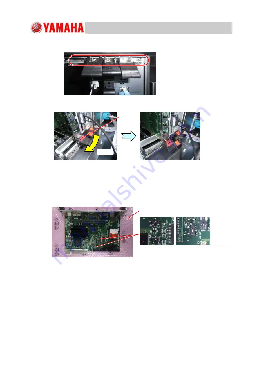
Loosen the setscrews on the upper and lower sides of the PCB to be removed, using a
precision screwdriver, etc.
(4)
Pressing the red section on the lever, push down the lever.
(Press the levers on the upper and lower sections at the same time).
Fig.D18
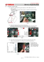
4.2.3. Handling of Control Board
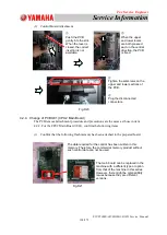
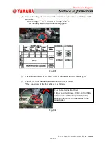
(1) Do not touch the electronic components placed section directly. Grab the levers and
put the section on an antistatic sheet, etc. (Wear an antistatic belt).
Fig.D19
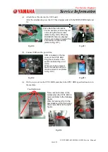
Note:
The basic settings for each board are described in Chapter 5.
However, the settings might be different
depending on the design changes. Therefore, make a note of the settings as currently as possible.
Antistatic sheet,
polyethylene, etc.
Note:
Check carefully the PCB settings such as for Dip
SW and jumper pin, and make a note of them.
Push
Down


