For Service Engineer
Service Information
SI1705004E-00=SIGMA-G5SII Service Manual
121/273
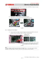
Fig. D3
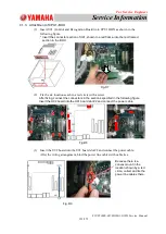
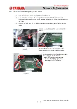
4.1.2. Removal of Control Board U91 or U92
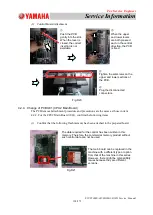
Fig. D4
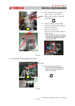
(3) Disconnect the power connectors.
4pin × 1, 8pin × 1 and 20pin × 1
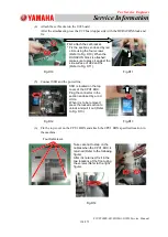
(4) Remove the two setscrews and pull
out the BOX.
(5) Incline the drawn out CPU BOX
toward the right hand side and keep it
as shown in the figure.
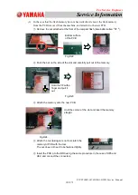
Remove the upper plate.
(Setscrews in four locations; Refer to
the left figure).
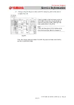
* Because SSD has been attached to
the upper side of the cover, open the
cover, with careful attention to the
wiring for the SSD.
Setscrews
Setscrews
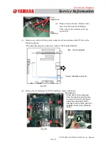
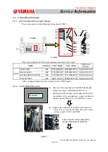
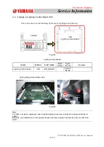
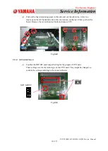
(1) Remove the board fixing block.
* Loosening the two setscrews, can
remove the board fixing block as
shown in the figure.


