background image

IMPORTANT SAFETY INSTRUCTIONS

Caution-i

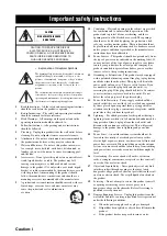
Explanation of Graphical Symbols

The lightning flash with arrowhead symbol, within an 
equilateral triangle, is intended to alert you to the 
presence of uninsulated “dangerous voltage” within 
the product’s enclosure that may be of sufficient 
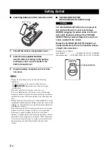
magnitude to constitute a risk of electric shock to 
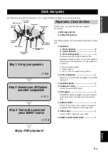
persons.

The exclamation point within an equilateral triangle 
is intended to alert you to the presence of important 
operating and maintenance (servicing) instructions in 
the literature accompanying the appliance.

1

Read Instructions – All the safety and operating instructions 
should be read before the product is operated.

2

Retain Instructions – The safety and operating instructions 
should be retained for future reference.

3

Heed Warnings – All warnings on the product and in the 
operating instructions should be adhered to.

4

Follow Instructions – All operating and use instructions 
should be followed.

5

Cleaning – Unplug this product from the wall outlet before 
cleaning. Do not use liquid cleaners or aerosol cleaners.

6

Attachments – Do not use attachments not recommended by 
the product manufacturer as they may cause hazards.

7

Water and Moisture – Do not use this product near water – 
for example, near a bath tub, wash bowl, kitchen sink, or 
laundry tub; in a wet basement; or near a swimming pool; 
and the like.

8

Accessories – Do not place this product on an unstable cart, 
stand, tripod, bracket, or table. The product may fall, 
causing serious injury to a child or adult, and serious 
damage to the product. Use only with a cart, stand, tripod, 
bracket, or table recommended by the manufacturer, or sold 
with the product. Any mounting of the product should 
follow the manufacturer’s instructions, and should use a 
mounting accessory recommended by the manufacturer.

9

A product and cart combination should be moved with care. 
Quick stops, excessive force, and uneven surfaces may 
cause the product and cart combination to 
overturn.

10

Ventilation – Slots and openings in the cabinet are provided 
for ventilation and to ensure reliable operation of the 
product and to protect it from overheating, and these 
openings must not be blocked or covered. The openings 
should never be blocked by placing the product on a bed, 
sofa, rug, or other similar surface. This product should not 
be placed in a built-in installation such as a bookcase or rack 
unless proper ventilation is provided or the manufacturer’s 
instructions have been adhered to.

11

Power Sources – This product should be operated only from 
the type of power source indicated on the marking label. If 
you are not sure of the type of power supply to your home, 
consult your product dealer or local power company. For 
products intended to operate from battery power, or other 
sources, refer to the operating instructions.

12

Grounding or Polarization – This product may be equipped 
with a polarized alternating current line plug (a plug having 
one blade wider than the other). This plug will fit into the 
power outlet only one way. This is a safety feature. If you 
are unable to insert the plug fully into the outlet, try 
reversing the plug. If the plug should still fail to fit, contact 
your electrician to replace your obsolete outlet. Do not 
defeat the safety purpose of the polarized plug.

13

Power-Cord Protection – Power-supply cords should be 
routed so that they are not likely to be walked on or pinched 
by items placed upon or against them, paying particular 
attention to cords at plugs, convenience receptacles, and the 
point where they exit from the product.

14

Lightning – For added protection for this product during a 
lightning storm, or when it is left unattended and unused for 
long periods of time, unplug it from the wall outlet and 
disconnect the antenna or cable system. This will prevent 
damage to the product due to lightning and power-line 
surges.

15

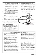
Power Lines – An outside antenna system should not be 
located in the vicinity of overhead power lines or other 
electric light or power circuits, or where it can fall into such 
power lines or circuits. When installing an outside antenna 
system, extreme care should be taken to keep from touching 
such power lines or circuits as contact with them might be 
fatal.

16

Overloading – Do not overload wall outlets, extension 
cords, or integral convenience receptacles as this can result 
in a risk of fire or electric shock.

17

Object and Liquid Entry – Never push objects of any kind 
into this product through openings as they may touch 
dangerous voltage points or short-out parts that could result 
in a fire or electric shock. Never spill liquid of any kind on 
the product.

18

Servicing – Do not attempt to service this product yourself 
as opening or removing covers may expose you to 
dangerous voltage or other hazards. Refer all servicing to 
qualified service personnel.

19

Damage Requiring Service – Unplug this product from the 
wall outlet and refer servicing to qualified service personnel 
under the following conditions:

a)

When the power-supply cord or plug is damaged,

b)

If liquid has been spilled, or objects have fallen into the 
product,

c)

If the product has been exposed to rain or water,

Important safety instructions

CAUTION

CAUTION: TO REDUCE THE RISK OF 

ELECTRIC SHOCK, DO NOT REMOVE 

COVER (OR BACK). NO USER-SERVICEABLE 

PARTS INSIDE. REFER SERVICING TO 

QUALIFIED SERVICE PERSONNEL.

RISK OF ELECTRIC SHOCK 

DO NOT OPEN

Содержание RXV661BL

Страница 1: ...ROISE CROIZAT BP70 CROISSY BEAUBOURG 77312 MARNE LA VALLEE CEDEX02 FRANCE YAMAHA ELECTRONICS UK LTD YAMAHA HOUSE 200 RICKMANSWORTH ROAD WATFORD HERTS WD18 7GQ ENGLAND YAMAHA SCANDINAVIA A B J A WETTERGRENS GATA 1 BOX 30053 400 43 VÄSTRA FRÖLUNDA SWEDEN YAMAHA MUSIC AUSTRALIA PTY LTD 17 33 MARKET ST SOUTH MELBOURNE 3205 VIC AUSTRALIA 2007 All rights reserved RX V661 Printed in Malaysia WJ69940 RX V...

Страница 2: ... you are not sure of the type of power supply to your home consult your product dealer or local power company For products intended to operate from battery power or other sources refer to the operating instructions 12 Grounding or Polarization This product may be equipped with a polarized alternating current line plug a plug having one blade wider than the other This plug will fit into the power o...

Страница 3: ...tion to Article 820 40 of the NEC that provides guidelines for proper grounding and in particular specifies that the cable ground shall be connected to the grounding system of the building as close to the point of cable entry as practical FCC INFORMATION for US customers 1 IMPORTANT NOTICE DO NOT MODIFY THIS UNIT This product when installed as indicated in the instructions contained in this manual...

Страница 4: ...y Yamaha will not be held responsible for any damage resulting from use of this unit with a voltage other than specified 13 To prevent damage by lightning keep the power cord and outdoor antennas disconnected from a wall outlet or the unit during a lightning storm 14 Do not attempt to modify or fix this unit Contact qualified Yamaha service personnel when any service is needed The cabinet should n...

Страница 5: ...et tuning 51 Selecting preset stations 52 Exchanging preset stations 52 XM Satellite Radio tuning 53 Connecting the XM Mini Tuner Dock 53 Activating XM Satellite Radio 54 Basic XM Satellite Radio operations 54 Setting the XM Satellite Radio preset channels 56 Displaying the XM Satellite Radio information 57 Using iPod 58 Controlling iPod 58 Recording 60 Advanced sound configurations 61 Changing so...

Страница 6: ... Definition Multimedia Interface are trademarks or registered trademarks of HDMI Licensing LLC SILENT CINEMA is a trademark of YAMAHA CORPORATION The XM name and related logos are registered trademarks of XM Satellite Radio Inc Neural Surround name and related logos are trademarks owned by Neural Audio Corporation Notice About this manual y indicates a tip for your operation Some operations can be...

Страница 7: ... to connect a Yamaha iPod universal dock such as the YDS 10 sold separately which supports iPod Click and Wheel iPod nano and iPod mini Playback information displaying capability Battery charging capability Other features YPAO Yamaha Parametric Room Acoustic Optimizer for automatic speaker setup 192 kHz 24 bit D A converter OSD on screen display menus that allow you to optimize this unit to suit y...

Страница 8: ...rtment thoroughly before installing new batteries Do not throw away batteries with general house waste dispose of them correctly in accordance with your local regulations If the remote control is without batteries for more than 2 minutes or if exhausted batteries remain in the remote control the contents of the memory may be cleared When the memory is cleared insert new batteries set up the remote...

Страница 9: ...Select an active subwoofer equipped with an RCA input jack Speaker cables 7 Subwoofer cable 1 Select a monaural RCA cable DVD player 1 Select DVD player equipped with coaxial digital audio output jack and composite video output jack Video monitor 1 Select a TV monitor video monitor or projector equipped with a composite video input jack Video cable 1 Select an RCA composite video cable Digital coa...

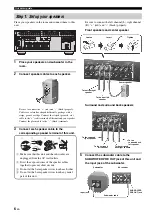
Страница 10: ...d and surround back speakers 5 Connect the subwoofer cable to the SUBWOOFER PRE OUT jack of this unit and the input jack of the subwoofer Step 1 Set up your speakers A B C PHONO CD PLAY IN OUT REC DVD DVD DTV CBL CD DVD MD CD R MD CD R DTV CBL DTV CBL DVR DVD MONITOR OUT DVR DVD IN OUT IN OUT DTV CBL DVR VCR MONITOR OUT MD CD R OUT IN VCR SB 8CH FRONT 6CH SINGLE CENTER CENTER S VIDEO VIDEO OUT SUR...

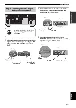
Страница 11: ... SB 8CH FRONT 6CH SINGLE CENTER CENTER S VIDEO VIDEO OUT SURROUND SUB WOOFER SUB WOOFER FRONT SURROUND SUR BACK MULTI CH INPUT ZONE 2 PRE OUT VIDEO OUT IN GND FRONT B ZONE2 FRONT A CENTER SURROUND PRESENCE EXTRA SP TRIGGER COMPONENT VIDEO AC OUTLETS SPEAKERS HDMI AUDIO ANTENNA AM GND FM UNBAL DIGITAL INPUT DIGITAL OUTPUT XM DOCK OUT REMOTE 12V 15mA MAX IN OUT SURROUND BACK BI AMP SINGLE OPTICAL CO...

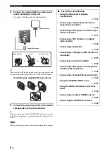
Страница 12: ...ing on the models Note Indoor FM antenna AM loop antenna Open the lever Insert Close the lever For further connections Using the other kind of speaker combinations P 12 Connecting a video monitor via various ways of the connection P 18 Connecting a DVD player via various ways of the connection P 19 Connecting a DVD recorder or a digital video recorder P 20 Connecting a set top box P 20 Connecting ...

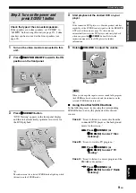
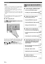
Страница 13: ...urther information 5 Rotate 0VOLUME to adjust the volume When you change the input source or sound field program the SCENE mode is deactivated and the indicator on the selected SCENE button turns off Using the other SCENE buttons In the following cases try pressing the corresponding SCENE button to enjoy the playback of the desired sources Case A I want to listen to a music disc from the connected...

Страница 14: ...te control To turn on this unit from the standby mode press the desired FSCENE buttons or FSCENE or AMAIN ZONE ON OFF on the front panel or HPOWER on the remote control See page 25 for details Notes What do you want to do with this unit Customizing the SCENE templates Using various SCENE templates P 33 Creating your original SCENE templates P 36 Using various input sources Basic controls of this u...

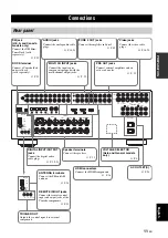
Страница 15: ...5mA MAX IN OUT 75 XM jack U S A and Canada models only Connect the XM Mini Tuner Dock sold separately P 53 DOCK terminal Connect a Yamaha iPod universal dock sold separately P 23 AUDIO jacks Connect the analog audio cable plugs P 18 21 MULTI CH INPUT jacks Connect the input source component equipped with the multi channel output jacks P 22 ZONE 2 OUT jacks Connect the amplifier in Zone 2 P 89 PRE ...

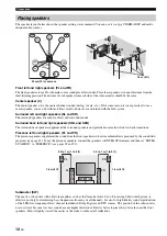
Страница 16: ...ack transitions Presence left and right speakers PL and PR The presence speakers supplement the sound from the front speakers with extra ambient effects produced by the sound field programs see page 42 To use the presence speakers connect the speakers to EXTRA SP terminals and then set EXTRA SP ASSIGN to PRESENCE see pages 29 and 72 Subwoofer SW The use of a subwoofer with a built in amplifier suc...

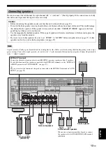
Страница 17: ...turn on this unit Use the magnetically shielded speakers If this type of speaker still creates interference with the monitor place the speakers away from the monitor If you are to use 6 ohm speakers be sure to set SP IMP to 6Ω MIN before using this unit see page 25 4 ohm speakers can be also used as the front speakers see page 93 Note SUB WOOFER PRE OUT FRONT B ZONE2 FRONT A CENTER SURROUND PRESEN...

Страница 18: ...ws you to make bi amplification connections to one speaker system Check if your speakers support bi amplification To make the bi amplification connections use the FRONT and SURROUND BACK terminals as shown below To activate the bi amplification connections set BI AMP to ON in ADVANCED SETUP see page 95 When you make the conventional connection make sure that the shorting bars are put into the term...

Страница 19: ...t using the optical jack be sure to put the cap back in place This cap protects the jack from dust Video jacks This unit has three types of video jacks Connection depends on the availability of input jacks on your video monitor VIDEO jacks For conventional composite video signals transmitted via composite video cables S VIDEO jacks For S video signals separated into the luminance Y and chrominance...

Страница 20: ...se noise Audio signals input at input jacks other than the HDMI IN 1 or HDMI IN 2 jack of this unit cannot be digitally output at the HDMI OUT jack If you turn off the power of the video monitor connected to the HDMI OUT jack via a DVI connection this unit may fail to establish the connection to the component Information on HDMI Audio signal types Audio signal formats Compatible HDMI components 2c...

Страница 21: ...he priority order of the input signals is as follows 1 COMPONENT VIDEO 2 S VIDEO 3 VIDEO Digital video signals input at the HDMI IN 1 or HDMI IN 2 jack cannot be output from analog video output jacks This unit does not accept analog component video signals with 1080p of resolution The OSD signal is not output at the VCR OUT DVR OUT and HDMI MONITOR OUT jacks and is not recorded This unit does not ...

Страница 22: ...y are in the standby mode In this case the HDMI indicator flashes irregularly When you connect your TV monitor or projector via HDMI connection the OSD does not appear In such cases connect the TV monitor or projector via component S video or video connection Connect the input source components to the HDMI IN 1 or HDMI IN 2 jack to display the video images on the video monitor connected to the HDM...

Страница 23: ...gned to each DIGITAL INPUT or DIGITAL OUTPUT jack select the corresponding setting for OPTICAL OUT OPTICAL IN or COAXIAL IN in I O ASSIGNMENT see page 78 If you connect your DVD player to both the DIGITAL INPUT OPTICAL and the DIGITAL INPUT COAXIAL jacks priority is given to the signals input at the DIGITAL INPUT COAXIAL jack Connecting a DVD player Connecting other components Notes Make sure that...

Страница 24: ...deo out Video out Audio out DVD recorder PVR or VCR S video in Video out Audio out Audio in Video in Component video out DVD recorder PVR Audio in Video in S video out B DTV CBL DTV CBL DTV CBL DTV CBL S VIDEO VIDEO VIDEO COMPONENT VIDEO HDMI AUDIO DIGITAL INPUT OPTICAL DTV CBL IN2 4 Y PB PR O V L R S PR PB Y Satellite receiver cable TV receiver or HDTV decoder HDMI out Component video out Audio o...

Страница 25: ... only compatible with a turntable with an MM or a high output MC cartridge To connect a turntable with a low output MC cartridge to the PHONO jacks use an in line boosting transformer or an MC head amplifier When you connect both the DIGITAL INPUT OPTICAL jack and the DIGITAL INPUT COAXIAL jack to an audio component the priority is given to the DIGITAL INPUT COAXIAL jack Notes PHONO CD PLAY IN OUT...

Страница 26: ...r or an external decoder This unit is equipped with 6 additional input jacks left and right FRONT CENTER left and right SURROUND and SUBWOOFER for discrete multi channel input from a multi format player external decoder sound processor or pre amplifier If you set INPUT CH to 8ch in MULTI CH SET see page 80 you can use the input jacks assigned as FRONT in MULTI CH SET see page 80 together with the ...

Страница 27: ... of the components to control the components by using the SCENE feature If the component connected to the REMOTE OUT jack is not the Yamaha product set SCENE IR in the advanced setup menu to OFF see page 95 Use the VIDEO AUX jacks on the front panel to connect a game console or a video camera to this unit The audio signals input at the DOCK terminal on the rear panel take priority over the ones in...

Страница 28: ...et s is supplied when the main zone or Zone 2 is turned on However power to these outlet s is cut off when the main zone and Zone 2 are turned off or when BMASTER ON OFF on the front panel is pressed and released outward to the OFF position For information on the maximum power or the total power consumption of the components that can be connected to these outlet s see Specifications on page 108 Co...

Страница 29: ...ning off this unit Press BMASTER ON OFF on the front panel again to release it outward to the OFF position to turn off this unit AMAIN ZONE ON OFF on the front panel as well as HPOWER and GSTANDBY on the remote control are operational only when BMASTER ON OFF is pressed inward to the ON position As usual we recommend using the standby mode to turn off this unit Set the main zone to the standby mod...

Страница 30: ...orresponding cursor lights up to show the currently selected input source 8 YPAO indicator Lights up when you run AUTO SETUP and when the speaker settings set in AUTO SETUP are used without any modifications see page 28 9 Tuner indicators Lights up when this unit is in the FM AM or XM Satellite Radio tuning mode see pages 50 to 57 0 MUTE indicator Flashes while the MUTE function is on see page 40 ...

Страница 31: ...SENCE see pages 29 or 72 The remote control transmits a directional infrared ray Be sure to aim the remote control directly at the remote control sensor on this unit during operation Infrared window W Outputs infrared control signals Aim this window at the component you want to operate VTRANSMIT indicator Flashes while the remote control is sending infrared signals Operation mode selector K The fu...

Страница 32: ...ent 1 Make sure of the following check points before starting the AUTO SETUP operations Speakers are connected appropriately Headphones are disconnected from this unit This unit and the video monitor are turned on The connected subwoofer is turned on and the volume level is set to about half way or slightly less The crossover frequency controls of the connected subwoofer is set to the maximum The ...

Страница 33: ... when you change the setting of BI AMP in the advanced setup see page 95 or EXTRA SP ASSIGN in SOUND MENU see page 72 6 Press Dl h to select the desired setting of EQ and then press Dn Parametric equalizer type EQ Parametric equalizer adjusts the level of the specified frequency bands This unit automatically selects the crucial frequency bands for the listening room and adjusts the level of the se...

Страница 34: ...ays the speaker output level in the following order Lowest speaker output level Highest speaker output level If E 10 INTERNAL ERROR appears during the testing procedure restart from step 4 If you selected RELOAD in step 4 no test tones are output If an error occurs during the AUTO CHECK procedure the setup procedure is canceled and an error screen appears For details see If an error screen appears...

Страница 35: ...UTO SETUP results 12 Press DENTER to confirm your selection The top SET MENU display appears in the OSD 13 Press NSET MENU to exit from SET MENU 14 Disconnect the optimizer microphone from this unit The optimizer microphone is sensitive to heat Keep it away from direct sunlight and do not place it on top of this unit y If you change speakers speaker positions or the layout of your listening enviro...

Страница 36: ... SETUP procedure 1 Make sure the pointer is pointing at WARNING and then press DENTER to display the detailed information about the warning The number on the right of WARNING indicates the number of warning messages 2 Press Dl h repeatedly to toggle between the warning displays y For details about each warning message see the AUTO SETUP section in Troubleshooting on page 101 When the corresponding...

Страница 37: ...SCENE template appears in the front panel display 2 Rotate the IINPUT selector or set the operation mode selector to KAMP and then press Dl h to select the desired template 3 Press the FSCENE or FSCENE button again to confirm the selection The selected SCENE template is assigned to the SCENE button If you do not carry out any operation within 30 seconds from the last operation in these steps this ...

Страница 38: ... Action Game Playing RPG Playing DVD V AUX PHONO DTV CBL TUNER FM AM DOCK CD DVD DVR Video sources DVD video Recorded video TV programs Video games iPod Radio programs Music discs CD SACD or DVD Audio SCENE templates Which component do you like for playback Vinyl records Which source do you like to play back LP Record Listening XM Default SCENE buttons To enjoy XM Satellite Radio programs you need...

Страница 39: ...2ch STEREO Select this SCENE template when you play back music discs on your DVD player Disc Listening DVD 1 STEREO 7ch STEREO Select this SCENE template when you play back music sources on your DVD player as the background music CD Hifi Listening CD 1 PURE DIRECT Select this SCENE template when you enjoy the high fidelity sound of the music discs on your CD player CD Listening CD 1 STEREO 2ch STE...

Страница 40: ...the night listening mode to the MUSIC mode 4 Press the FSCENE button again to confirm the edit y An asterisk mark appears by the name of the original SCENE template Once the desired SCENE templates are assigned to the corresponding FSCENE buttons you need to set the input source of the SCENE template on the remote control See page 84 for details You can create a customized SCENE template for each ...

Страница 41: ...elector or press one of the sound field program selector buttons P repeatedly to select the desired sound field program The name of the selected sound field program appears in the front panel display See page 42 for details about sound field programs Sound field programs cannot be selected when the component connected to the MULTI CH INPUT jacks is selected as the input source see page 38 y Choose...

Страница 42: ...ff the volume level of this unit when you switch the front speaker setting Using the Zone B feature When you set FRONT B to ZONE B see page 72 you can use the speakers connected to the EXTRA SP speaker terminals in another room Zone B Press 1SPEAKERS on the front panel repeatedly to turn on or off the Zone B speakers When you activate the Zone B speakers all the speakers in the main room are muted...

Страница 43: ...2 Set the operation mode selector to KAMP and then press ODISPLAY on the remote control The current status screen appears in the OSD y You can select the amount of time that the current status is displayed in the OSD by using the OSD AMP parameter in OPTION MENU see page 81 The OSD signal is not output at the VIDEO output jacks and will not be recorded Selecting audio input jacks AUDIO SELECT AUTO...

Страница 44: ...select a video source and then an audio source y Set the BGV parameter in the MULTI CH SET menu to the desired setting to select the default background video input source of the MULTI CH INPUT sources see page 80 You can display the format sampling frequency channel bit rate and flag data of the current input signal 1 Set the operation mode selector to KAMP and then press NSET MENU on the remote c...

Страница 45: ...edly until SLEEP OFF appears in the front panel display The SLEEP indicator turns off and SLEEP OFF disappears from the front panel display after a few seconds y The sleep timer setting can also be canceled by pressing GSTANDBY or AMAIN ZONE ON OFF to set the main zone to the standby mode FORMAT Signal format When this unit cannot detect a digital signal it automatically switches to analog input S...

Страница 46: ...LTI CH INPUT jacks is selected as the input source see page 38 When you play back DTS 96 24 sources with any sound field program this unit applies the selected program without activating the DTS 96 24 decoder Sampling frequencies higher than 48 kHz are sampled down to 48 kHz or lower and then sound field programs are applied When the sampling frequency of the input sources are higher than 96 kHz t...

Страница 47: ...ZE LIVENESS DIALG LIFT CLASSICAL Chamber This program creates a relatively wide space with a high ceiling like an audience hall in a palace It offers pleasant reverberations that are suitable for courtly music and chamber music DSP LEVEL INIT DLY LIVENESS REV TIME REV DELAY REV LEVEL DIALG LIFT LIVE CLUB Cellar Club This program simulates a live house with a low ceiling and homey atmosphere A real...

Страница 48: ...ing and FPS games It uses the reflection data that limits the effects range per channel in order to offer a powerful playing environment with a being there feeling by enhancing various effects tones while maintaining a clear sense of directions DSP LEVEL P INIT DLY P ROOM SIZE S INIT DLY S ROOM SIZE SB INI DLY SB ROOM SIZE DIALG LIFT ENTERTAINMENT Roleplaying Game This sound field has been suitabl...

Страница 49: ...can enjoy a variety of cinematographically created virtual spaces reproduced with clear separation between dialog sound effects and background music DSP LEVEL P INIT DLY P ROOM SIZE S INIT DLY S ROOM SIZE SB INI DLY SB ROOM SIZE DIALG LIFT 4 MOVIE MOVIE Adventure This program is ideal for precisely reproducing the sound design of action and adventure movies The sound field restrains reverberations...

Страница 50: ...LENT CINEMA indicator lights up in the front panel display SILENT CINEMA does not activate when the component connected to the MULTI CH INPUT jacks is selected as the input source see page 38 SILENT CINEMA is not effective when the Pure Direct see page 48 or 2ch Stereo mode see page 49 is selected or when this unit is in the STRAIGHT mode see page 47 Note STEREO 2ch STEREO Use this program to mix ...

Страница 51: ...i channel sources are decoded straight into the appropriate channels without any additional effect processing Press ESTRAIGHT or SSTRAIGHT to select STRAIGHT Deactivating the STRAIGHT mode Press ESTRAIGHT or SSTRAIGHT so that STRAIGHT disappears from the front panel display The sound effect is turned back on Enjoying unprocessed input sources Straight decoding mode STRAIGHT ...

Страница 52: ...equency response BASS If you increase or decrease the high frequency or the low frequency sound to an extreme level the tonal quality of the surround speakers may not match TONE CONTROL is not effective when PURE DIRECT is selected or when MULTI CH INPUT is selected as the input source You can adjust the output level of each speaker while listening to a music source This is also possible when play...

Страница 53: ...GHT MUSIC when listening to music sources to preserve ease of listening for all sounds Select OFF if you do not want to use this feature y When a night listening mode is selected the NIGHT indicator lights up in the front panel display 2 Press Dl h to adjust the effect level while NIGHT CINEMA or NIGHT MUSIC is displayed in the front panel display Choices MIN MID MAX Select MIN for minimum compres...

Страница 54: ...lay tuning is not possible Press 2PRESET TUNING to turn the colon off 4 Press 5PRESET TUNING CH l h once to begin automatic tuning When this unit is tuned into a station the TUNED indicator lights up and the frequency of the received station is shown in the front panel display Press 5h to tune into a higher frequency Press 5l to tune into a lower frequency If the signal received from the station y...

Страница 55: ...s 2PRESET TUNING so that the colon disappears from the front panel display and then press 5PRESET TUNING CH l after pressing and holding 6MEMORY for more than 3 seconds Any stored station data existing under a preset station number is cleared when you store a new station under the same preset station number If the number of received stations does not reach 40 E8 automatic preset tuning automatical...

Страница 56: ...pears in the front panel display and changes each time you press the button 2 Press 5PRESET TUNING CH l h on the front panel or DPRESET CH k n on the remote control to select the desired preset station number 1 to 8 The preset station group and number appear in the front panel display along with the station band and frequency You can exchange the assignments of two preset stations with each other ...

Страница 57: ...tely Other fees and taxes including a one time activation fee may apply Subscription fee is consumer only All fees and programming subject to change Subscriptions subject to Customer Agreement available at xmradio com US residents and xmradio ca Canadian residents Only available in the 48 contiguous United States and Canada 2006 XM Satellite Radio Inc All rights reserved All other trademarks are t...

Страница 58: ...KSOURCE 1 Rotate the IINPUT selector or press AXM to select XM as the input source The cursor on the left of the XM indicator lights up in the front panel display and the XM Satellite Radio information such as channel number channel name category artist name or song title for the currently selected channel appears in the front panel display y When you select XM as the input source this unit automa...

Страница 59: ...ess 2SEARCH MODE or NSRCH MODE repeatedly to select PRESET SEARCH 2 Press 4CATEGORY or DA E CAT l h repeatedly to change the preset channel group A to E 3 Press 5PRESET TUNING CH l h or DPRESET CH k n repeatedly to change the preset channel number 1 to 8 y You can also select the preset channel number directly by pressing the numeric buttons 1 to 8 B Direct number access mode 1 Press NSRCH MODE on...

Страница 60: ... a preset channel group A to E while the MEMORY indicator is flashing The preset channel group letter appears in the front panel display 4 Press 5PRESET TUNING CH l h or DPRESET CH k n repeatedly to select a preset channel number 1 to 8 while the MEMORY indicator is flashing The preset channel number appears in the front panel display 5 Press 6MEMORY or EXM MEMORY to set the selected XM Satellite ...

Страница 61: ...ith a space If you press 7DISPLAY or ODISPLAY while the XM Satellite Radio information display is scrolling from right to left in the front panel display the XM Satellite Radio information display mode toggles as described above Displaying the XM Satellite Radio information in the OSD Press 7DISPLAY or ODISPLAY The following screen is displayed in the OSD y To turn off the OSD press 7DISPLAY or OD...

Страница 62: ...n while this unit charges the battery of the connected iPod when this unit is in the standby mode You can control your iPod when V AUX is selected as the input source The operations of your iPod can be done with the aid of the OSD of this unit menu browse mode or without it simple remote mode Controlling iPod in the simple remote mode You can perform the basic operations of your iPod play stop ski...

Страница 63: ...o play albums in random order y When Shuffle is set to a setting other than Off appears in the top right corner while songs or albums are being shuffled Repeat Repeat Use this feature to set this unit to repeat one song or a sequence of songs Choices Off One All Select Off to deactivate this feature Select One to set this unit to repeat one song Select All to set this unit to repeat a sequence of ...

Страница 64: ...vides only an S video or a composite video signal you can only record an S video or a composite video signal on your VCR The analog audio signals input at the DOCK terminal can be output at the analog AUDIO OUT REC jacks for recording Check the copyright laws in your country to record from CDs radio etc Recording of copyrighted material may infringe copyright laws y Do a test recording before you ...

Страница 65: ...on and control range of each sound field parameter see page 63 When you set a sound field parameter to a value other than the initial factory settings an asterisk mark appears by the sound field parameter name in the OSD The available sound field parameters for some of the sound field programs may be displayed on more than one page in the OSD In this case press Dk n to scroll through pages If you ...

Страница 66: ...rogram is too weak You cannot recognize any difference between the sound field programs Decrease the value of DSP LEVEL when The sound is vague You feel that the additional sound effect is excessive Control range 6 dB to 3 dB Adjusting the vertical dialogue position DIALG LIFT Use this feature to adjust the vertical position of the dialogues in movies The ideal position of the dialogues is at the ...

Страница 67: ...e apparent distance from the source sound by adjusting the delay between the direct sound and the first reflection heard by the listener The smaller the value the closer the sound source seems to the listener y When you adjust the initial delay parameters we also recommend adjusting the corresponding room size parameters likewise This adjustment is especially effective for the CINEMA DSP programs ...

Страница 68: ...ially effective for the CINEMA DSP programs Control range 0 1 to 2 0 LIVENESS S LIVENESS SB LIVENESS Liveness Surround and surround back sound field liveness Adjusts the reflectivity of the virtual walls in the hall by changing the rate at which the early reflections decay The early reflections of a sound source decay much faster in a room with acoustically absorbent wall surfaces than in one whic...

Страница 69: ...eginning of the direct sound and the beginning of the reverberation sound The larger the value the later the reverberation sound begins A later reverberation sound makes you feel as if you are in a larger acoustic environment Control range 0 to 250 ms REV LEVEL Reverberation level Adjusts the volume of the reverberation sound The larger the value the stronger the reverberation becomes Control rang...

Страница 70: ...Select OFF not to bypass the decoders the DSP processors and the tone control circuitry when BASS and TREBLE are set to 0 dB When multi channel signals Dolby Digital and DTS are input they are downmixed to 2 channels and output from the front left and right speakers The low frequency signals input from the front left and right speakers are redirected to the subwoofer in the following cases LFE BAS...

Страница 71: ...Music PL IIx Music SURROUND DECODE PANORAMA 9 SUR DECODE Dolby Pro Logic IIx or Dolby Pro Logic II processing for music sources The Pro Logic IIx decoder is not available when SB L R SP is set to NONE see page 73 Available sound field parameters see page 63 Program description Remote control button Name of the program Category of the program 9 SUR DECODE 9 SUR DECODE 9 SUR DECODE 9 SUR DECODE SURR...

Страница 72: ...setting STD standard PRO LOGIC IIx Music PRO LOGIC II Music CENTER WIDTH Pro Logic IIx Music and Pro Logic II Music center width Moves the center channel output completely towards the center speaker or towards the front left and right speakers A larger value moves the center channel output towards the front left and right speakers Control range 0 center channel sound is output only from the center...

Страница 73: ... the speakers for low frequency signal output the crossover frequency and the assignment of the EXTRA SP terminal 72 B SPEAKER LEVEL Adjusts the output level of each speaker 74 C SP DISTANCE Adjusts the distance of each speaker 75 D EQUALIZER Adjusts the tonal quality of the center speaker 75 E LFE LEVEL Adjusts the output level of the LFE channel for Dolby Digital or DTS signals 76 F DYNAMIC RANG...

Страница 74: ...Y GUARD Locks sound field program parameters and other SET MENU settings 82 C AUDIO SELECT Designates the default audio input jack select setting for the input sources when you turn on the power of this unit 82 D PARAM INI Initializes the parameters of a group of sound field programs 82 E ZONE 2 SET Adjusts the Zone 2 parameters 82 F XM RADIO SET Displays the current reception level of the XM Sate...

Страница 75: ...wing displays are examples where SOUND MENU is selected 4 Press Dk n repeatedly and then press DENTER to select and enter the desired submenu The following display is an example where LFE LEVEL is selected 5 Press Dk n to select the desired parameter and then Dl h to change the parameter settings 6 Press NSET MENU to exit from SET MENU Using SET MENU SET MENU AUTO SETUP MANUAL SETUP A SIGNAL INFO ...

Страница 76: ...en the FRONT B speakers are set in the main room Select ZONE B if the FRONT B speakers are set in another room If FRONT A is turned off and FRONT B is turned on all the speakers including the subwoofer in the main room are muted and this unit outputs sound at the FRONT B terminals only If you connect headphones to the PHONES jack of this unit the sound is output from both the headphones and the EX...

Страница 77: ...en the surround speakers are small Select SML small When you do not use the surround speakers Select NONE none This unit is set to the Virtual CINEMA DSP mode see page 46 and SUR B L R SP is automatically set to NONE Surround back left right speakers SUR B L R SP Choices NONE SMLx1 SMLx2 LRGx1 LRGx2 When the surround back left and right speakers are large Select LRGx2 large x 2 When the single sur...

Страница 78: ...se this feature to select the crossover frequency of all the speakers set to SML or SMALL or to NONE in SPEAKER SET see page 73 All frequencies below the selected frequency will be sent to the subwoofer or to the speakers set to LRG or LARGE in SPEAKER SET see page 73 Choices 40Hz 60Hz 80Hz 90Hz 100Hz 110Hz 120Hz 160Hz 200Hz Subwoofer phase SUBWOOFER PHASE Use this feature to switch the phase of y...

Страница 79: ... Use this feature to select the type of equalizer Choices AUTO PEQ CENTER GEQ EQ OFF Select AUTO PEQ to use the parametric equalizer adjusted in AUTO SETUP see page 28 Select CENTER GEQ to adjust the built in 5 frequency band graphic equalizer so that the tonal quality of the center speaker matches that of the front left and right speakers Press Dk n to display the graphic equalizer screen Select ...

Страница 80: ...ount of dynamic range compression to be applied to your speakers or headphones This setting is effective only when this unit is decoding Dolby Digital and DTS signals Choices MIN STD MAX Select MIN minimum if you regularly listen at low volume levels Select STD standard for general use Select MAX maximum to preserve the greatest amount of dynamic range Speaker SP Adjusts the speaker compression He...

Страница 81: ... at the HDMI IN jacks of this unit are not output to the HDMI component connected to the HDMI OUT jack on the rear panel of this unit Select OTHER to play back HDMI audio signals on another HDMI component connected to the HDMI OUT jack The HDMI video signals input at the HDMI IN 1 or HDMI IN 2 jack of this unit are always output at the HDMI OUT jack of this unit Extended surround decoders I EXTD S...

Страница 82: ... to AUTO Use this menu to reassign the input output jacks select the input mode or rename the input source Input output assignment A I O ASSIGNMENT Use this feature to assign the input output jacks according to the component to be used if the initial settings of this unit do not correspond to your needs Change the following parameters to reassign the respective jacks and effectively connect more c...

Страница 83: ...e front panel display y This feature is useful when you change the input or output assignment for digital jacks and component video input jacks You can only rename DOCK when iPod is stationed in the Yamaha Universal Dock connected to this unit 1 Press one of the input selector buttons A on the remote control to select the input source you want to change the name of 2 Press Dl h to place the _ unde...

Страница 84: ...matically detect input signal types and select the appropriate input mode Select DTS if you want this unit to select DTS as the input mode Multi channel input settings E MULTI CH SET Use this feature to set the function of the multi channel input BGV BGV Use this feature to select the video source played in the background of the sources input from the MULTI CH INPUT jacks Choices DVD DTV CBL V AUX...

Страница 85: ...D display time OSD SOURCE Use this feature to set the amount of time to display the XM Satellite Radio information or iPod menu in the OSD after you perform a certain operation Choices ON 10s 30s Select ON to display the OSD continuously during an operation Select 10s to turn off the OSD 10 seconds after you perform a certain operation Select 30s to turn off the OSD 30 seconds after you perform a ...

Страница 86: ...responding sound field program selector buttons on the remote control to select the sound field program that you want to initialize An asterisk appears to the left of the sound field program names that have been changed from their initial factory settings Choices CLASSICAL LIVE CLUB ENTERTAINMENT MOVIE STEREO ENHANCER SUR DECODE You cannot automatically revert to the previous parameter settings on...

Страница 87: ...he XM Satellite Radio signals see page 53 For the best reception orient the XM Mini Tuner so that a value of 60 or more is displayed here Display status NONE 0 to 100 NONE is displayed if the XM Mini Tuner Dock is not connected to this unit In this case check the antenna connections see page 53 iPod universal dock setting G DOCK SET Charge on standby STANDBY CHARGE Use this feature to select wheth...

Страница 88: ...omize the input source of the selected SCENE template you must set the input source of the SCENE template on the remote control to operate the input source component correctly 1 Press the desired FSCENE button on the remote control 2 Press and hold the FSCENE button and the desired input selector button A The VTRANSMIT indicator flashes twice 3 Keep holding down the buttons pressed in step 2 until...

Страница 89: ...er components Notes 5 6 7 8 9 0 10 ENT 1 2 3 4 MENU TITLE SET MENU LEVEL CLASSICAL LIVE CLUB ENTERTAIN MOVIE STEREO ENHANCER STRAIGHT PURE DIRECT SUR DECODE NIGHT SLEEP DISPLAY RETURN BAND SRCH MODE XM MEMORY REC SCENE A E CAT ENTER PRESET CH VOLUME TV VOL TV CH TV MUTE TV INPUT MUTE AMP SOURCE TV CD CD R DVD DTV MD MULTI CH IN AUDIO SEL CBL TUNER V AUX DOCK DVR VCR XM PHONO STANDBY POWER POWER PO...

Страница 90: ...DECODE NIGHT SLEEP DISPLAY RETURN BAND SRCH MODE XM MEMORY REC SCENE A E CAT ENTER PRESET CH 1 2 3 4 2 8 9 7 3 4 6 5 1 Remote control DVD player recorder VCR Digital TV Cable TV LD player CD player MD CD recorder Tuner iPod 1 AV POWER Power 1 Power 1 Power 2 Power 1 Power 1 Power 1 2 1 9 0 10 Numeric buttons Numeric buttons Numeric buttons Numeric buttons Numeric buttons Numeric buttons Preset sta...

Страница 91: ...r on the remote control flashes twice and the remote control code for the selected component is set y Refer to List of remote control codes at the end of this manual If the manufacturer of your component has more than one code try each of them until you find the correct one If you do not press any buttons within 30 seconds in step 3 the setup process is canceled If this happens repeat the setup pr...

Страница 92: ...1 The VTRANSMIT indicator on the remote control flashes twice and all the remote control codes previously set are cleared and reset to the initial factory settings y If you do not press any buttons within 30 seconds after step 2 the clearing process is canceled In this case repeat the clearing procedure Resetting all remote control codes TRANSMIT STANDBY POWER POWER POWER AV TV TRANSMIT CODE SET F...

Страница 93: ... nearest authorized Yamaha dealer or service center about the Zone 2 connections that best meet your requirements Some Yamaha models are able to connect directly to the REMOTE jacks of this unit If you own these products you may not need to use an infrared signal emitter Up to 6 Yamaha components can be connected as shown below Using the external amplifier Connect the amplifier receiver in the sec...

Страница 94: ...g in the front panel display Otherwise the Zone 2 mode is automatically canceled and this unit returns to the normal operation mode In this case repeat the Zone 2 selection procedure Controlling Zone 2 with the front panel Turning on Zone 2 Press 8ZONE 2 ON OFF to turn on Zone 2 y 8ZONE 2 ON OFF is operational only when BMASTER ON OFF on the front panel is pressed inward to the ON position Once BM...

Страница 95: ... Press and hold HPOWER or GSTANDBY and then press A to set the remote control to the Zone 2 mode Press HPOWER when the main zone is turned on Press GSTANDBY when the main zone is turned off The VTRANSMIT indicator on the remote control lights up while the remote control is set to the Zone 2 mode When the remote control is set to the Zone 2 mode HPOWER GSTANDBY JVOLUME LMUTE and the input selector ...

Страница 96: ...ess BMASTER ON OFF on the front panel to release it outward to the OFF position to turn off this unit 2 Press and hold CTONE CONTROL and then press BMASTER ON OFF inward to the ON position to turn on this unit This unit turns on and the advanced setup menu appears in the front panel display 3 Rotate the DPROGRAM selector to select the parameter you want to adjust The name of the selected parameter...

Страница 97: ...ote control AMP ID codes You need to set the remote control AMP ID code for the remote control 1 Press UCODE SET using a ballpoint pen or a similar object The VTRANSMIT indicator on the remote control flashes twice 2 Press the numeric buttons B to enter the code number 00001 or 00002 The VTRANSMIT indicator on the remote control flashes twice and the AMP ID code is changed 1 The remote control set...

Страница 98: ... XM ID codes You need to set the remote control XM ID code for the remote control 1 Press AXM to select XM as the input source 2 Press UCODE SET using a ballpoint pen or a similar object The VTRANSMIT indicator on the remote control flashes twice 3 Press the numeric buttons B to enter the code number 82006 or 82007 The VTRANSMIT indicator on the remote control flashes twice and the XM ID code is c...

Страница 99: ...E function set SCENE IR to OFF Bi amplifier setting BI AMP Use this feature to activate or deactivate the bi amplifier function see page 14 Choices ON OFF Select ON if you want to activate the bi amplifier function SUR B L R SP is set to NONE automatically and this unit outputs the front channel audio signals at the SURROUND BACK speaker terminals Select OFF if you want to deactivate the bi amplif...

Страница 100: ... microphone 31 Audio input jack select is set to HDMI COAX OPT or ANALOG Set Audio input jack select to AUTO 39 Audio input jack select is set to ANALOG while playing a source encoded in Dolby Digital or DTS Set Audio input jack select to AUTO or COAX OPT 39 No appropriate input source has been selected Select an appropriate input source with the INPUT selector on the front panel or the input sele...

Страница 101: ...ld programs are turned off Press ESTRAIGHT to turn them on 47 You are using a source or program combination that does not output sound from all channels Try another sound field program 37 EXTRA SP ASSIGN is set to a setting other than PRESENCE Set EXTRA SP ASSIGN to PRESENCE 72 No sound is heard from the surround speakers SUR L R SP in SET MENU is set to NONE Set SUR L R SP to SML or LRG 73 This u...

Страница 102: ...the sound is distorted The component connected to the AUDIO OUT REC jacks of this unit is turned off Turn on the power of the component The sound effects cannot be recorded It is not possible to record the sound effects with a recording component A source cannot be recorded by a digital recording component connected to the DIGITAL OUTPUT jack The source component is not connected to the DIGITAL IN...

Страница 103: ...uality directional FM antenna Use the manual tuning method 50 There is distortion and clear reception cannot be obtained even with a good FM antenna There is multi path interference Adjust the antenna position to eliminate multi path interference The desired station cannot be tuned into with the automatic tuning method The signal is too weak Use a high quality directional FM antenna Use the manual...

Страница 104: ...ected category Select another channel category by pressing 4CATEGORY on the front panel or DA E CAT l h on the remote control repeatedly 55 Problem Cause Remedy See page The remote control does not work or function properly Wrong distance or angle The remote control will function within a maximum range of 6 m 20 ft and no more than 30 degrees off axis from the front panel 27 Direct sunlight or lig...

Страница 105: ... unit 23 Try resetting your iPod Unknown iPod The iPod being used is not supported by this unit Only iPod Click and Wheel iPod nano and iPod mini are supported iPod connected Your iPod is properly stationed in a Yamaha iPod universal dock such as the YDS 10 sold separately connected to the DOCK terminal of this unit and the connection between your iPod and this unit is complete Disconnected Your i...

Страница 106: ...kers when you use surround back speakers 13 E 7 NO MIC The optimizer microphone was unplugged during the AUTO SETUP procedure Connect the supplied optimizer microphone to the OPTIMIZER MIC jack on the front panel 28 E 8 NO SIGNAL The optimizer microphone does not detect test tones Check the microphone setting 28 Check the speaker connections and placement 13 E 9 USER CANCEL The AUTO SETUP procedur...

Страница 107: ...nel to release it outward to the OFF position 1 Press BMASTER ON OFF on the front panel to release it outward to the OFF position to turn off this unit 2 Press and hold CTONE CONTROL and then press BMASTER ON OFF inward to the ON position to turn on this unit This unit turns on and the advanced setup menu appears in the front panel display 3 Rotate the DPROGRAM selector to select PRESET 4 Press CT...

Страница 108: ...his unit any sound environment from monaural up to a 5 1 channel configuration can be freely selected for your enjoyment Dolby Digital EX Dolby Digital EX creates 6 full bandwidth output channels from 5 1 channel sources This is done using a matrix decoder that derives 3 surround channels from the 2 in the original recording For the best results Dolby Digital EX should be used with movie sound tra...

Страница 109: ...nted as 0 1 because it only enforces a low frequency range compared to the full range reproduced by the other 5 6 channels in Dolby Digital or DTS 5 1 6 1 channel systems Neo 6 Neo 6 decodes the conventional 2 channel sources for 6 channel playback by the specific decoder It enables playback with the full range channels with higher separation just like digital discrete signal playback There are tw...

Страница 110: ...berations in your listening room you would be able to create your own listening environment The acoustics in your room could be changed to those of a concert hall a dance floor or a room with virtually any size at all This ability to create sound fields at will is exactly what Yamaha has done with the digital sound field processor CINEMA DSP Since the Dolby Surround and DTS systems were originally...

Страница 111: ...factor The width of the specified frequency band is referred to as the Q factor This parameter is adjustable between the values 0 5 and 10 YPAO adjusts frequency characteristics to suit your listening requirements using a combination of the above three parameters Frequency Gain and Q factor for each equalizer band in this unit s parametric equalizer This unit has 7 equalizer bands for each channel...

Страница 112: ...r models 86 dB or more CD etc Effect Off 250 mV to Front L R 100 dB or more Residual Noise IHF A Network Front L R 150 µV or less Channel Separation 1 kHz 10 kHz PHONO shortened to Front L R 60 dB 55 dB or more CD etc 5 1 kΩ shortened to Front L R 60 dB 45 dB or more Volume Control MUTE 80 dB to 16 5 dB Tone Control Front L R BASS Boost Cut 10 dB 50 Hz BASS Turnover Frequency 350 Hz TREBLE Boost C...

Страница 113: ...els AC 230 V 50 Hz Power Consumption U S A and Canada models 380 W 480 VA Other models 390 W Standby Power Consumption 0 1 W or less Maximum Power Consumption General model only 6ch 10 THD 800 W AC Outlets U S A Canada and China models 2 Total 100 W maximum Asia General and Europe models 2 Total 50 W maximum Australia and U K models 1 Total 100 W maximum Dimensions W x H x D 435 x 171 x 393 mm 17 ...

Страница 114: ...FECT PURE DIRECT STRAIGHT PHONES SILENT CINEMA ON OFF AUDIO SELECT TONE CONTROL OPTIMIZER MIC 1 2 3 4 SPEAKERS PRESET TUNING EDIT FM AM A B C D E CATEGORY MEMORY TUNING AUTO MAN L DISPLAY ON OFF ZONE 2 CONTROL ZONE l PRESET TUNING CH h MAIN ZONE MASTER ON OFF G 1 2 3 4 5 6 7 8 9 0 A C D E H B I J F ...

Страница 115: ... 8 10 7 0 9 6 5 SLEEP MOVIE ENTERTAIN LIVE CLUB CLASSICAL ENT PURE DIRECT STRAIGHT STEREO ENHANCER NIGHT SUR DECODE MENU TITLE SET MENU SRCH MODE XM MEMORY LEVEL DISPLAY RETURN BAND A E CAT ENTER PRESET CH CD CD R TUNER XM V AUX DVD DVR VCR DTV 4 3 2 1 8 7 0 9 6 5 MOVIE ENTERTAIN LIVE CLUB CLASSICAL PURE DIRECT STRAIGHT STEREO ENHANCER NIGHT SUR DECODE G K L M J I H N E F D A U V W B C O P Q R S T...

Страница 116: ...assignment 78 COAXIAL IN Input output assignment 79 COAXIAL INPUT jack assignment Input output assignment 79 COMPONENT VIDEO jack assignment Input output assignment 78 COMPONENT VIDEO jacks 15 Compressed Music Enhancer 46 Compressed Music Enhancer effect level Sound field parameter 66 Connection AM antenna connection 24 Connection audio components 21 Connection CD player 21 Connection CENTER PRE O...

Страница 117: ...on 23 iPod universal dock setting 83 iPod universal dock setting Option menu 83 iPod use 58 J Jacks 15 L LEVEL Auto setup parameter 30 LFE indicator 27 LFE BASS OUT Speaker settings 74 LFE Bass out Speaker settings 74 LIVE CLUB Sound field category 43 LIVENESS Sound field parameter 64 Liveness Sound field parameter 64 Low frequency effect level Sound menu 76 LVL Auto setup result 30 M Manual prese...

Страница 118: ...E 2 9 SCENE 3 9 SCENE 4 9 SCENE IR code setting Advanced setup 95 SCENE IR Advanced setup 95 SCENE template rename 36 Sci Fi Sound field program 45 Selection Audio input jacks 39 Selection Front speaker set 38 Selection MULTI CH INPUT component 38 Selection SCENE template 33 SET MENU usage 71 Set top box connection 20 Shuffle iPod playback 59 SILENT CINEMA 46 SILENT CINEMA indicator 26 SIZE Auto s...

Страница 119: ...cator 26 VOLTAGE SELECTOR 4 Volume level 30 VOLUME level indicator 26 Volume Trim Input menu 80 W WIRING Auto setup parameter 30 X XM ANTENNA XM Radio setting 83 XM Mini Tuner Dock 53 XM Radio antenna XM Radio setting 83 XM Radio setting Option menu 83 XM satellite radio activation 54 XM Satellite Radio display 57 XM satellite radio tuning 53 Y YPAO indicator 26 Z Zone 2 89 Zone 2 Initial volume Z...

Страница 120: ... NETWORK SYSTEM 11505 11005 10775 11775 DISHPRO 11505 11005 10775 11775 DX ANTENNA 11530 ECHOSTAR 11505 11005 10775 11775 ESAT 10879 EXPRESSVU 10775 11775 FOXTEL 10879 11356 FUNAI 11377 GE 10392 10566 GOI 10775 11775 HITACHI 10749 10819 10214 11250 11518 11523 11525 HOUSTON 10775 HTS 10775 11775 HUGHES NETWORK SYSTEMS 11142 10749 11749 11442 JVC 10775 10492 11507 11531 11532 11775 LG 11226 MAGNAVO...

Страница 121: ...ICE 20264 IMA 20178 20179 20180 20236 INFINITY 20054 INNOVA 20037 INSIGNIA 20171 INTEQ 20017 20145 JBL 20054 JCB 20000 JENSEN 20761 20815 20817 JIL 20030 JINXING 20037 JUTAN 20030 JVC 20030 20036 20053 20054 20160 20653 20731 21172 21253 21428 KAMP 20017 20180 KAWASHO 20030 KEC 20060 20180 KENWOOD 20030 20180 KLH 20156 20180 20765 20767 KLOSS 20030 KONKA 20180 KTV 20030 20180 20463 LARK 20154 LG 2...

Страница 122: ...0037 20051 21756 TEAC 20037 20154 20264 20706 TECHNICS 20051 20054 20250 TECHNOL ACE 20179 TECHNOVOX 20030 TECHWOOD 20051 20060 20250 TEKNIKA 20054 20060 20092 20150 20178 20179 20180 20186 20463 TELECOLOR 20017 TELEFUNKEN 20702 TELETON 20186 TEVION 20037 THOMAS 20047 20178 THOMSON 20047 21447 TMK 20178 20180 20236 TNCI 20017 TOCOM 20156 TOSHIBA 21704 21656 21456 21356 21265 21256 21173 21169 2115...

Страница 123: ...38 KODAK 30035 30037 KTV 30000 LG 30037 30240 30038 LIFETEC 30348 LINKSYS 31972 LLOYD S 30240 30000 30038 LOEWE 30081 LOGIK 30240 30000 LXI 30037 30000 30042 30067 M ELECTRONIC 30240 MAGNASONIC 30037 30240 30000 31278 MAGNAVOX 30035 30037 30048 30039 30081 30240 30000 30226 30618 31781 MAGNIN 30240 MARANTZ 30035 30081 30038 31381 MARTA 30037 MATSUI 30037 30209 30348 MATSUSHITA 30035 30162 30081 30...

Страница 124: ...A 40831 CINEVISION 40876 40869 CITIZEN 41003 41277 CLAIRTONE 40571 COBY 40778 41086 41107 CRAIG 40831 CREATIVE 40503 40539 CURTIS MATHES 41087 CYBERHOME 40816 40874 41023 41024 41117 41129 CYTRON 40705 DAEWOO 40784 40705 40770 40869 41169 41172 DANSAI 40770 DAYTEK 40872 DECCA 40770 DENON 40490 40634 41282 41634 DENVER 40778 DIGITREX 40672 DISNEY 40675 41270 DIVIDO 40705 DUAL 40675 DURABRAND 41127 ...

Страница 125: ...50675 51556 51642 52002 SONY 51033 51069 51070 51431 SYLVANIA 50675 TOSHIBA 51510 51639 VICTOR 51275 YAMAHA 52001 ZENITH 50741 CD PLAYER ADC 60018 ADCOM 60234 AIWA 60157 AKAI 60083 60643 61688 ALBA 60625 ANAM NATIONAL 60362 ARCAM 60157 AUDIO RESEARCH 60157 CAIRN 60157 CALIFORNIA AUDIO LABS 60029 60303 CAMBRIDGE SOUNDWORKS 60157 CARVER 60157 CCE 60643 CLASSIC 61297 CURTIS MATHES 60032 DENON 60873 6...

Страница 126: ...DSTAR 80281 GRUNDIG 80281 HARMAN KARDON 80110 HITACHI 80386 INTEGRA 80135 80842 81298 81320 JBL 80110 JVC 81058 80074 80262 80464 81374 81495 81665 KAWASAKI 81390 KENWOOD 80027 80186 80262 KLH 81390 LG 80281 MAGNAVOX 81189 81269 80531 81266 MARANTZ 81189 81269 80039 81671 MCS 80039 MICROMEGA 81189 MYRYAD 81189 ONKYO 80135 80380 80842 81298 81320 81677 OPTIMUS 81023 80158 80074 80014 80080 80121 80...

Страница 127: ...ROISE CROIZAT BP70 CROISSY BEAUBOURG 77312 MARNE LA VALLEE CEDEX02 FRANCE YAMAHA ELECTRONICS UK LTD YAMAHA HOUSE 200 RICKMANSWORTH ROAD WATFORD HERTS WD18 7GQ ENGLAND YAMAHA SCANDINAVIA A B J A WETTERGRENS GATA 1 BOX 30053 400 43 VÄSTRA FRÖLUNDA SWEDEN YAMAHA MUSIC AUSTRALIA PTY LTD 17 33 MARKET ST SOUTH MELBOURNE 3205 VIC AUSTRALIA 2007 All rights reserved RX V661 Printed in Malaysia WJ69940 RX V...

Страница 128: ... PHONES SILENT CINEMA ON OFF AUDIO SELECT TONE CONTROL OPTIMIZER MIC 1 2 3 4 SPEAKERS PRESET TUNING EDIT FM AM A B C D E CATEGORY MEMORY TUNING AUTO MAN L DISPLAY ON OFF ZONE 2 CONTROL ZONE l PRESET TUNING CH h MAIN ZONE MASTER ON OFF G 1 2 3 4 5 6 7 8 9 0 A C D E H B I J F 00_Sheet_RX V861_661_U book Page 1 Friday December 8 2006 5 49 PM ...

Страница 129: ...CAL ENT PURE DIRECT STRAIGHT STEREO ENHANCER NIGHT SUR DECODE MENU TITLE SET MENU SRCH MODE XM MEMORY LEVEL DISPLAY RETURN BAND A E CAT ENTER PRESET CH CD CD R TUNER XM V AUX DVD DVR VCR DTV 4 3 2 1 8 7 0 9 6 5 MOVIE ENTERTAIN LIVE CLUB CLASSICAL PURE DIRECT STRAIGHT STEREO ENHANCER NIGHT SUR DECODE G K L M J I H N E F D A B C O P Q R S T U V W WK14480 Printed in Malaysia a 00_Sheet_RX V861_661_U ...

Страница 130: ...ock connected to this unit When the SCENE mode is deactivated and your iPod is stationed in the Yamaha Universal Dock this unit selects DOCK as the input source automatically Correct 2 You can select V AUX as the input source even if your iPod is stationed in the Yamaha Universal Dock connected to this unit WK52460 Printed in Malaysia U ...

Отзывы: