background image

PSR-A300

9

5.

Speaker

 (Time required: About 3 minutes)

5-1

Remove the lower case assembly. (See procedure 1)

5-2

Remove the four (4) screws marked [30]. The
speaker can then be removed. (Fig. 2)

The right and left speakers can be removed in the
same way.

6.

SP Grille

 (Time required: About 3 minutes)

6-1

Remove the lower case assembly. (See procedure 1)

6-2

Set the four (8) [A]s parallel to the groove in the upper
case assembly and remove the SP grille. (Fig. 2)

The right and left SP grilles can be removed in the
same way.

7.

Lower Case Keyboard Assembly

 (Time required: About 2 minutes)

7-1

Remove the lower case assembly. (See procedure 1)

7-2

Remove the two (2) screws marked [240C] and
screw marked [270B]. The lower case keyboard
assembly can then be removed. (Fig. 2)

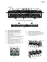
8.

PN1 Circuit Board, PN2 Circuit Board

(Time required: About 3 minutes each)

8-1

Remove the lower case keyboard assembly.
(See procedure 7)

8-2

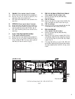
PN1 Circuit Board

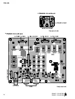
8-2-1 Remove the eight (8) screws marked [150D]. The

PN1 circuit board can then be removed. (Fig. 5)

8-3

PN2 Circuit Board

8-3-1 Remove the five (5) screws marked [150E]. The PN2

circuit board can then be removed. (Fig. 5)

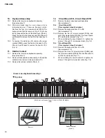
9.

PB Circuit Board

(Time required: About 3 minutes)

9-1

Remove the lower case keyboard assembly.
(See procedure 7)

9-2

Remove the two (2) screws marked [150F]. Then,
while sliding outward the wheel assembly connected
to the PB circuit board, pull the PB circuit board
upward. (Fig. 5)

The wheel assembly is not part of the PB circuit

board. When replacing the PB circuit board, remove
the wheel assembly and install it to the new circuit
board.

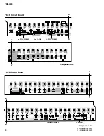
PN1

[150E]

Bottom view

DMLCD

PNAM

2/3

PNAM

1/3

1/3

[150D]

[150D]

[150F]

PN2

3/3

PNAM

PB

Wheel Assembly

(Fig.5)

[150]: Bind Head Tapping Screw-B 3.0X8 MFZN2W3 (WE774300)

Содержание PortaTone PSR-A300

Страница 1: ...NEL LAYOUT 4 CIRCUIT BOARD LAYOUT WIRING 5 BLOCK DIAGRAM 6 DISASSEMBLY PROCEDURE 7 LSI PIN DESCRIPTION 12 IC BLOCK DIAGRAM 14 CIRCUIT BOARDS 15 TEST PROGRAM 21 BACKUP INITIALIZATION 24 TRANSFERRING DA...

Страница 2: ...y an authorized Yamaha Retailer or the appointed service representative IMPORTANT This presentation or sale of this manual to any individual or firm does not constitute authorization certifi cation re...

Страница 3: ...es Main voice Volume Octave Chorus Send Level Dual voice Voice Volume Octave Chorus Send Level Split voice Voice Volume Octave Chorus Send Level Reverb Type Reverb level Chorus Type Panel Sustain Harm...

Страница 4: ...button o STYLE button 0 VOICE button 1 Number buttons 0 9 YES NO 2 DEMO button 3 METRONOME ON OFF button When the Song mode 4 A B REPEAT button 5 REW button 6 FF button 9 PAUSE button When the Style m...

Страница 5: ...CN1 61H CN3 DMLCD CN831 DMLCD CN832 DMLCD CN833 PNAM1 3 CN101 PNAM1 3 CN102 DMLCD CN131 PNAM3 3 CN402 Speaker L Speaker R DMLCD CN531 PNAM2 3 CN502 PNAM2 3 CN504 PNAM2 3 CN505 DMLCD CN631 DMLCD CN901...

Страница 6: ...3D 3 3D 5D 3 3D 5D 5D 5A1 5A1 5A2 5A2 L R L R B IC101 3P IC132 3P IC431 16P IC901 6P IC432 8P IC701 80P IC131 3P TR101 102 4 12cm 4 12cm RXD0 TXD0 SCLK PF0 IRQ0 Power SS PF0 Power Select IRQ0 Power S...

Страница 7: ...CD Time required About 3 minutes 3 1 Remove the lower case assembly See procedure 1 3 2 Remove the DMLCD circuit board See procedure 2 3 3 Remove the LCD holder and rubber connector 3 4 Remove the bac...

Страница 8: ...1 3 can then be removed Fig 2 4 4 PNAM circuit board 2 3 Time required About 3 minutes 4 4 1 Remove the nine 9 screws marked 150C The PNAM circuit board 2 3 can then be removed Fig 2 30 30 A A DMLCD...

Страница 9: ...Circuit Board PN2 Circuit Board Time required About 3 minutes each 8 1 Remove the lower case keyboard assembly See procedure 7 8 2 PN1 Circuit Board 8 2 1 Remove the eight 8 screws marked 150D The PN...

Страница 10: ...move the rubber contacts Photo 2 12 Circuit Board 61L Circuit Board 61H 12 1 Remove the lower case keyboard assembly See procedure 7 12 2 Circuit Board 61L Time required About 6 minutes 12 2 1 Remove...

Страница 11: ...in the upper right direction to remove it Fig 8 13 6 Remove the hook for the spring terminal B to pull it out from inside Fig 8 B Spring Terminal C Spring Terminal D 13 1 Remove the battery lid assem...

Страница 12: ...B0 I O 58 PB1 I O 59 PB2 I O 60 PB3 I O Parallel port B 61 PB4 I O 62 PB5 I O 63 PB6 I O 64 PB7 SYI I O Parallel port B 65 VSS Ground 66 IOVDD Power supply 67 LBN LWRN PF6 O Low byte enable 68 UBN UWR...

Страница 13: ...al for LCD driver outout Display data interface Read write Enable Data interface Data interface FUNCTION PIN NO 41 42 43 44 45 46 47 48 49 50 51 52 53 54 55 56 57 58 59 60 61 62 63 64 65 66 67 68 69 7...

Страница 14: ...Modulator Modulator P Interface De emphasis Control Clock Divider Audio Data Interface 8X Interpolator 8X Interpolator SCF SCF CSN NJM4580E X2331A00 Dual Operational Amplifier DMLCD IC432 1 2 3 4 V 8...

Страница 15: ...ON FF REW A B REPEAT PNAM1 3 Circuit Board 2NA WE00540 2 CIRCUIT BOARDS DMLCD Circuit Board X5910C0 17 PB Circuit Board X5067A0 20 PN1 Circuit Board X6095A0 19 PN2 Circuit Board X6095A0 20 PNAM 1 3 Ci...

Страница 16: ...IT PEVERB ON OFF SPLIT ON OFF DUAL ON OFF HARMONY ON OFF TOUCH ON OFF METRONOME ON OFF DEMO 7 4 1 0 8 5 2 9 6 3 SUSTAIN MIDI OUT IN to DMLCD CN631 to DMLCD CN531 PNAM2 3 Circuit Board to PNAM1 3 CN401...

Страница 17: ...PSR A300 17 to PNAM2 3 CN601 to PNAM2 3 CN501 to 61H CN2 to 61H CN1 to 61L CN5 to PNAM1 3 CN103 to PB CN1 DMLCD Circuit Board Component side Pattern side 2NA WE00520 1...

Страница 18: ...PSR A300 18 B B to DMLCD CN833 to 61H CN3 B B to DMLCD CN831 to 61L CN4 to DMLCD CN832 A A A A Component side Component side 61H 2NAKB V869540 61L 2NAKB V869520 61H Circuit Board 61L Circuit Board...

Страница 19: ...PSR A300 19 ORIENTAL SCALE SETTING C C D D C C to PNAM2 3 CN504 D D PN1 Circuit Board Component side Pattern side 2NA WE16730 1...

Страница 20: ...PSR A300 20 to PNAM2 3 CN505 ORIENTAL SCALE MEMORY 1 2 3 4 PN2 Circuit Board Component side Pattern side PB Circuit Board Component side PN2 2NA WE16730 1 PB 2NA WC36570 1 to DMLCD CN901 PITCH BEND...

Страница 21: ...L 45 0dBu or less PHONES R 1 5dBu 2dB 8 015 Output L Connect the level meter with JIS C filter to the L R terminals of the PHONES OUTPUT 33 of load Set the MASTER VOLUME to the maximum level and check...

Страница 22: ...at PD1 OK is displayed on the LCD when finished 15 033 PB Chk Checks the wheel Press the START STOP button and the center of the wheel is detected Make sure that C3 is played when the wheel is turned...

Страница 23: ...D 2 E2 F2 F 2 G2 G 2 A2 A 2 B2 C3 C 3 D3 Turn SW Name LCD Display Note Number 28 29 30 31 32 33 34 35 36 37 38 39 40 41 42 43 44 45 46 47 48 49 50 51 52 53 54 REC PAUSE START STOP PORTABLE GRAND SOUND...

Страница 24: ...e highest black keys on the keyboard and turn the power on by pressing the STANDBY ON switch When you execute the Flash Clear operation Song data you have purchased and downloaded will also be cleared...

Страница 25: ...oft Downloader operation are as follows Installing Musicsoft Downloader http music yamaha com download OS Windows 98SE Me 2000 XP Home Edition XP Professional CPU 233 MHz or higher Intel Pentium Celer...

Страница 26: ...n the followingcases During Demo playbaack During Style playback During Song playback During recording NOTE Close the window to exit from the Musicsoft Downloader and re enable control of the instrume...

Страница 27: ...8 o x Data Entry LSB 7 10 o o Control 11 x 1 o Expression 64 o o Sustain Change 71 73 74 x 1 o Prog o 0 127 o 0 127 Change True System Exclusive o o Song Pos x x Common Song Sel x x Tune x x System Cl...

Страница 28: ...Volume Values for ll are ignored MIDI Master Tuning F0H 43H 1nH 27H 30H 00H 00H mm ll cc F7H This message simultaneously changes the tuning value of all channels The values of mm and ll are used for M...

Страница 29: ...econd letter of the shaded part number is O not zero The second letter of the shaded part number is I not one M South African model O Chinese model Q South east Asia model T Taiwan model U U S A model...

Страница 30: ...320 330 390 390 150 150 340 350 380 380 400 340b 340a 400 150 150 150 150 150 260 270 270 280 280a 280b 280c 240 240 240 250 L30 L20 L30 L20 L30 L20 L40 L10 L50 30 20 190 210 220 240 200 140 3 3 140...

Страница 31: ...50 Lower Case Keyboard Ass y WD89530 260 Lower Case Assembly 270 Bind Head Tapping Screw B 3 0X30 MFZN2W3 3 280 Battery Lid Assembly 280a Battery Cover WD87980 280b Battery Cushion WHITE WD87990 280c...

Страница 32: ...MK1 12P L 220 40 Connector Assembly MK2 5P L 250 50 Connector Assembly MK3 7P L 190 60 Foot T1 6 3 01 70 Spring Terminal A 80 Spring Terminal B 90 Spring Terminal C 3 100 Spring Terminal D 2 110 Nonwo...

Страница 33: ...04 150b Circuit Board 61H 16N2M C61 P2 04 150c Connector Assembly 16N 2M C61 L 210 01 150d Felt U 02 160 Felt L 02 170 Rubber Sheet 01 180 Bind Head Tapping Screw B 3 0X8 MFZN2Y 7 01 190 Bind Head Tap...

Страница 34: ...tor SL chip 100P 50V J RECT 01 C0436 Ceramic Capacitor SL chip 680P 50V J RECT 01 0439 Ceramic Capacitor SL chip 680P 50V J RECT 01 C0440 Electrolytic Cap chip 4 7 50V UWX1H4 01 C0441 Electrolytic Cap...

Страница 35: ...470 0K 63M J RECT 01 R0312 Carbon Resistor chip 470 0K 63M J RECT 01 R0313 Carbon Resistor chip 47 0 63M J RECT 01 R0435 Carbon Resistor chip 8 2K 63M J RECT 01 0438 Carbon Resistor chip 8 2K 63M J R...

Страница 36: ...212 LED Red TL 20346D R F SETTING TR201 Transistor Array IMH10A T110 05 203 Transistor Array IMH10A T110 05 WA504 Connector Assembly ORIPN1 11P WE16450 Circuit Board PN2 WE16730 X6095A0 CN301 Cable Ho...

Страница 37: ...C0423 Electrolytic Cap 47 00 16 0V RX TP 01 C0423 Electrolytic Cap 47 00 16 0V TP C0501 Semiconductive Cera Cap 0 1000 25V Z FORM 01 C0501 Semiconductive Cera Cap 0 1000 25V Z RX TP 01 C0502 Electroly...

Страница 38: ...0102 Carbon Resistor 180 0 1 6J 26TP R0104 Carbon Resistor 47 0K 1 6J 26TP R0105 Carbon Resistor 3 3K 1 6 J 26TP R0107 Carbon Resistor 10 0K 1 6J 26TP R0108 Carbon Resistor 22 0K 1 6J 26TP R0109 Carbo...

Страница 39: ...SPR 2P L 220 WE14130 WA501 Connector Assembly PN1 16P L 100 WE14080 WA502 Connector Assembly PN2 10P L 340 WE13970 WA601 Connector Assembly JACK 9P L 70 WE14060 Circuit Board 61H 16N2M C61 P2 V869540...

Страница 40: ...S OUTPUT IN OUT MIDI SUSTAIN DC IN 12V BATTERY OR MASTER VOLUME PITCH BEND STANDBY ON C4 C6 C1 B3 SPEAKER R SPEAKER L to LCD BACK LIGHT POWER SUPPLY POWER SUPPLY 61H 61L 28CC1 8822437 28CC1 8822436 PN...

Отзывы: