
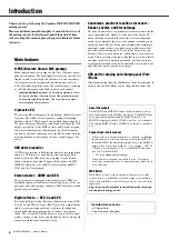


MGP32X/MGP24X Owner’s Manual
9
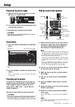
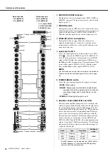
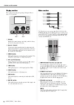
Setup
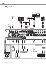
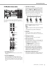
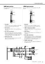
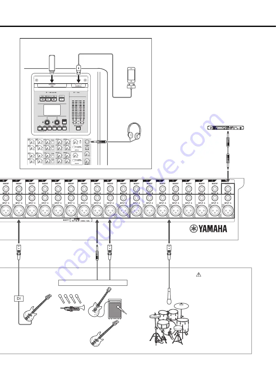
USB device
iPod/iPhone
Headphones
Compressor
Instrument, Microphone
Microphone
x 8
Drum
Bass
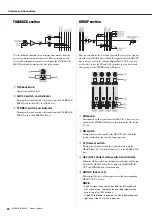
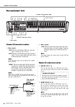
Rear panel
*The illustrations show the
panel of the MGP32X.
Top panel
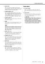
CAUTION
• When using a condenser
microphone, set the +48V
phantom switch to ON
(page 11).
* If electric guitars and basses can be con-
nected directly to the mixer’s inputs, use a
DI box (direct box) or amp simulator
between the instrument and the mixer.
Содержание MGP32X
Страница 1: ...EN Owner s Manual PRECAUTIONS pages 4 to 5 Setup pages 7 to 9 Troubleshooting pages 40 to 41...
Страница 47: ...MGP32X MGP24X Owner s Manual 47 Appendix Dimensions MGP32X MGP24X Unit mm 1027 169 819 169 565 565...
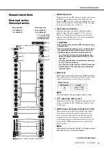
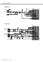
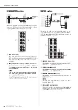
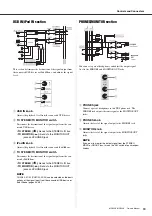
Страница 52: ...Appendix MGP32X MGP24X Owner s Manual 52 Block Diagram and Level Diagram...
Страница 53: ...MGP32X MGP24X Owner s Manual 53 Appendix...
Страница 54: ...MGP32X MGP24X Owner s Manual 54...


