ABS (ANTI-LOCK BRAKE SYSTEM) (for YP125RA)
8-125
EAS2DM1129
[B-3] DELETING THE FAULT CODES
To delete the fault codes, use the Yamaha diagnostic tool. For information about deleting the fault
codes, refer to the operation manual of the Yamaha diagnostic tool.
After the deletion procedure is finished, make sure that all of the fault codes displayed using the
Yamaha diagnostic tool have been deleted.
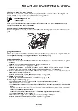
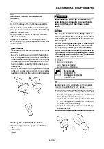
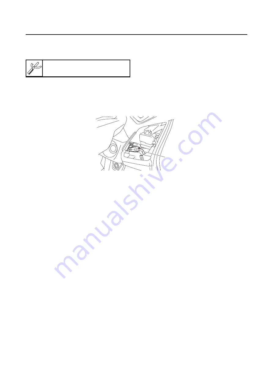
Connecting the Yamaha diagnostic tool
Remove the protective cap “1”, and then connect the Yamaha diagnostic tool to the ABS test coupler
(4P).
EAS2DM1130
[C-1] FINAL CHECK
Check the vehicle and finish the service according to the following procedures. If the procedures are
not completed normally, start the procedures over from the beginning.
Checking procedures
1. Check the brake fluid level in the front brake master cylinder reservoir and rear brake master cylinder
reservoir.
Refer to “CHECKING THE BRAKE FLUID LEVEL” on page 3-10.
2. Check the wheel sensors for proper installation.
Refer to “INSTALLING THE FRONT WHEEL (FRONT BRAKE DISCS) (for YP125RA)” on page
4-25 and “INSTALLING THE REAR WHEEL (REAR BRAKE DISC)” on page 4-29.
3. Perform brake line routing confirmation. If the reaction force is incorrect, the brake hoses and brake
pipes are not connected correctly.
Refer to “HYDRAULIC UNIT OPERATION TESTS” on page 4-65.
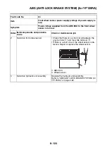
4. Delete the fault codes.
Refer to “[B-3] DELETING THE FAULT CODES” on page 8-125.
5. Checking the ABS warning light.
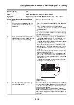
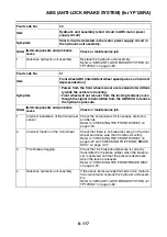
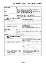
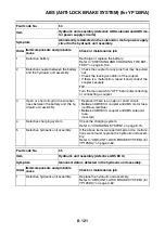
If the ABS warning light does not go off, the following are the probable causes.
• The malfunction is not corrected.
• There is a break in the wire harness between the ABS ECU and the meter assembly (ABS warning
light).
Check for continuity between the white/red terminal of the ABS ECU coupler and the white/red ter-
minal of the meter assembly coupler.
If there is no continuity, the wire harness is defective. Replace the wire harness.
• The meter assembly circuit is defective.
• The ABS warning light circuit in the hydraulic unit assembly is defective.
Refer to “CHECKING THE ABS WARNING LIGHT” on page 4-68.
Yamaha diagnostic tool
90890-03215
1
Содержание MBK XMAX 2014
Страница 1: ...2014 SERVICE MANUAL YP125R YP125RA 2DM F8197 E0 ...
Страница 6: ......
Страница 8: ......
Страница 64: ...TIGHTENING TORQUES 2 17 Muffler tightening sequence 1 2 3 ...
Страница 72: ...LUBRICATION SYSTEM DIAGRAMS 2 25 EAS2DM1116 LUBRICATION SYSTEM DIAGRAMS 1 2 3 4 5 3 ...
Страница 73: ...LUBRICATION SYSTEM DIAGRAMS 2 26 1 Camshaft 2 Crankshaft 3 Oil pump 4 Oil filter 5 Oil strainer ...
Страница 78: ...CABLE ROUTING 2 31 Steering head front view 1 2 3 4 5 6 8 8 A 7 7 ...
Страница 80: ...CABLE ROUTING 2 33 Front brake left side view for YP125R 1 2 2 1 1 2 2 D E A B C ...
Страница 82: ...CABLE ROUTING 2 35 Front brake left side view for YP125RA 2 1 1 2 1 2 2 A B D E C ...
Страница 84: ...CABLE ROUTING 2 37 Engine and rear brake left side and right side view for YP125R B 2 1 2 1 2 A A 3 3 C ...
Страница 86: ...CABLE ROUTING 2 39 Engine and rear brake left side and right side view for YP125RA 1 2 1 2 2 A A B 3 4 3 4 4 ...
Страница 92: ...CABLE ROUTING 2 45 Frame right side view 3 2 4 1 2 3 A B 6 5 3 A B 3 3 2 3 3 A A B A B B 3 ...
Страница 94: ...CABLE ROUTING 2 47 Engine right side view 6 6 6 6 C D C D D C 10 B 9 5 6 1 2 8 3 4 5 6 7 A ...
Страница 98: ...CABLE ROUTING 2 51 Frame left side view C D C D 2 1 E 1 2 D C 6 1 4 5 3 2 1 7 3 2 1 A B ...
Страница 100: ...CABLE ROUTING 2 53 Engine left side view 1 1 1 1 1 2 3 4 5 6 7 8 9 7 7 A B A B A B 1 ...
Страница 102: ...CABLE ROUTING 2 55 Frame top view 7 8 9 10 11 12 13 13 17 19 19 A D B C 14 C B 1 2 3 4 5 6 14 15 16 18 19 ...
Страница 104: ...CABLE ROUTING 2 57 Engine and frame top view 1 2 4 5 6 7 8 9 10 11 12 13 1 4 5 6 7 8 1 3 10 11 6 8 C 3 11 B A B A 3 ...
Страница 106: ...CABLE ROUTING 2 59 Rear brake right side view 2 2 2 2 2 2 1 1 2 3 A B C 3 ...
Страница 108: ...CABLE ROUTING 2 61 Hydraulic unit for YP125RA 3 2 1 2 3 3 2 2 3 2 2 2 3 3 3 4 4 1 1 4 2 6 B A A 5 1 5 1 5 ...
Страница 110: ...CABLE ROUTING 2 63 ...
Страница 228: ...REAR SHOCK ABSORBER ASSEMBLIES AND SWINGARM 4 89 ...
Страница 231: ......
Страница 291: ...CRANKSHAFT 5 60 a 1 ...
Страница 292: ...CRANKSHAFT 5 61 ...
Страница 302: ...WATER PUMP 6 9 ...
Страница 313: ......
Страница 329: ...CHARGING SYSTEM 8 16 2 AC magneto 3 Rectifier regulator 12 Battery 13 Main fuse 17 Frame ground ...
Страница 331: ...CHARGING SYSTEM 8 18 ...
Страница 349: ...COOLING SYSTEM 8 36 ...
Страница 391: ...FUEL PUMP SYSTEM 8 78 ...
Страница 400: ...IMMOBILIZER SYSTEM 8 87 a Light on b Light off ...
Страница 401: ...IMMOBILIZER SYSTEM 8 88 ...
Страница 405: ...ABS ANTI LOCK BRAKE SYSTEM for YP125RA 8 92 ...
Страница 439: ...ABS ANTI LOCK BRAKE SYSTEM for YP125RA 8 126 ...
Страница 464: ...ELECTRICAL COMPONENTS 8 151 ...
Страница 476: ......
Страница 477: ......
Страница 478: ......


