HTR-5920
9
HTR-5920
9
0
INPUT P.C.B.
AMP (4) P.C.B.
Note:
When assembling the AMP (4) P.C.B., be careful not to
bend the pin of the connectors (BN92 and BN94).
Note:
When assembling the AMP (4) P.C.B., be careful not to
bend the pin of the connectors (CN13 and CN14).
Heat Sink
AMP (1) P.C.B.
CN95
CN93
CN91
CN90
B
B
A
C
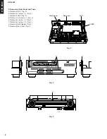
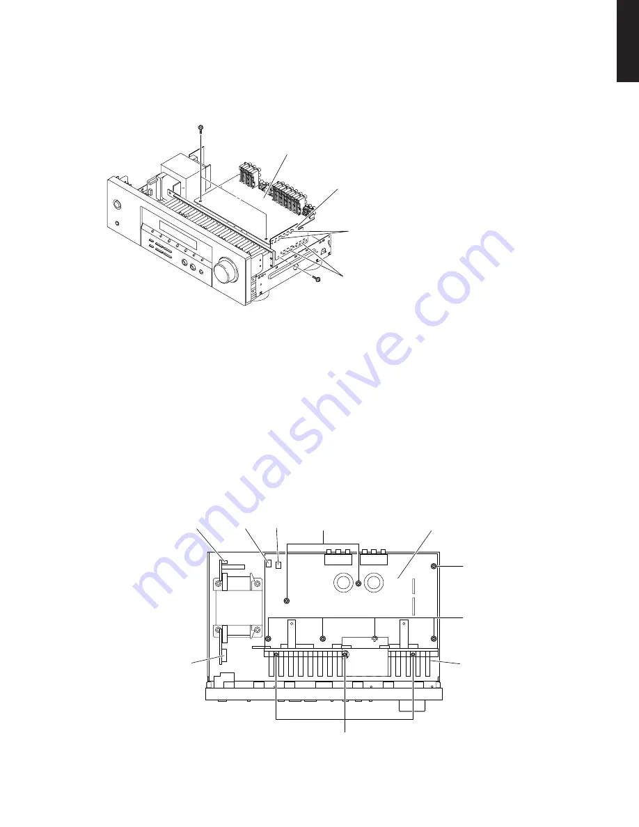
4. Removal of INPUT and AMP (4) P.C.B.s
a. Remove 1 screw (
9
) and 2 screws (
0
). (Fig. 5)
b. Remove INPUT and AMP (4) P.C.B.s. (Fig. 5)
Fig. 5
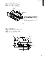
5. Removal of AMP (1) P.C.B.
a. Remove 2 screw (
A
) 5 screws (
B
) and 3 screw (
C
).
(Fig. 6)
b. Remove CN90, CN91, CN93 and CN95. (Fig. 6)
c. Remove AMP (1) P.C.B. with Heat Sink.
Fig. 6


