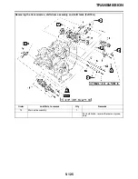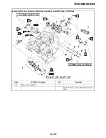
CRANKSHAFT
5-121
EAS26040
REMOVING THE CRANKSHAFT JOURNAL
BEARINGS
1. Remove:
• Crankshaft journal upper bearings
(from the upper crankcase)
• Crankshaft journal lower bearings
(from the lower crankcase)
TIP
Identify the position of each crankshaft journal
bearing so that it can be reinstalled in its original
place.
ET3P61029
CHECKING THE OIL NOZZLES
The following procedure applies to all of the oil
nozzles.
1. Check:
• Oil nozzle
Damage/wear
→
Replace the oil nozzle.
• Oil passage
Obstruction
→
Blow out with compressed air.
EAS26070
CHECKING THE CRANKSHAFT
1. Measure:
• Crankshaft runout
Out of specification
→
Replace the crank-
shaft.
2. Check:
• Crankshaft journal surfaces
• Crankshaft pin surfaces
• Bearing surfaces
Scratches/wear
→
Replace the crankshaft.
3. Measure:
• Crankshaft-journal-to-crankshaft-journal-
bearing clearance
Out of specification
→
Replace the crank-
shaft journal bearings.
NOTICE
ECA13920
Do not interchange the crankshaft journal
bearings. To obtain the correct crankshaft-
journal-to-crankshaft-journal-bearing clear-
ance and prevent engine damage, the crank-
shaft journal bearings must be installed in
their original positions.
▼▼▼
▼
▼ ▼▼▼
▼
▼ ▼▼▼
▼
▼ ▼▼▼
▼
▼ ▼▼▼
▼
▼ ▼▼▼
▼
▼▼▼
a. Clean the crankshaft journal bearings, crank-
shaft journals, and bearing portions of the
crankcase.
b. Place the upper crankcase upside down on a
bench.
c. Install the crankshaft journal upper bearings
“1” and the crankshaft into the upper crank-
case.
TIP
Align the projections “a” on the crankshaft jour-
nal upper bearings with the notches “b” in the up-
per crankcase.
d. Put a piece of Plastigauge
®
“2” on each
crankshaft journal.
TIP
Do not put the Plastigauge
®
over the oil hole in
the crankshaft journal.
Runout limit C
0.030 mm (0.0012 in)
Journal oil clearance (using plas-
tigauge
®
)
0.027–0.045 mm (0.0011–0.0018
in)
2 2
2 2
2 1
1 1
1
2
Содержание FJR13AY 2009
Страница 1: ...2009 SERVICE MANUAL FJR13AY C FJR13AEY C LIT 11616 22 73 3P6 28197 12 ...
Страница 6: ......
Страница 8: ......
Страница 80: ...LUBRICATION SYSTEM CHART AND DIAGRAMS 2 31 EAS20410 LUBRICATION DIAGRAMS 5 6 7 1 2 3 4 ...
Страница 82: ...LUBRICATION SYSTEM CHART AND DIAGRAMS 2 33 1 3 2 ...
Страница 83: ...LUBRICATION SYSTEM CHART AND DIAGRAMS 2 34 1 Main axle 2 Drive axle 3 Oil delivery pipe 1 ...
Страница 84: ...LUBRICATION SYSTEM CHART AND DIAGRAMS 2 35 6 5 4 3 2 1 ...
Страница 86: ...LUBRICATION SYSTEM CHART AND DIAGRAMS 2 37 1 2 3 4 5 6 7 8 9 ...
Страница 88: ...LUBRICATION SYSTEM CHART AND DIAGRAMS 2 39 4 5 3 2 1 9 8 6 7 ...
Страница 92: ...COOLING SYSTEM DIAGRAMS 2 43 A A 7 1 2 3 4 5 5 7 8 6 8 9 10 11 12 ...
Страница 98: ...CABLE ROUTING FJR13A 2 49 2 3 4 5 6 7 8 9 11 10 12 13 14 15 16 A B C D E F 1 1 ...
Страница 100: ...CABLE ROUTING FJR13A 2 51 1 2 3 4 5 6 7 8 A B C D E 9 10 11 12 13 ...
Страница 108: ...CABLE ROUTING FJR13A 2 59 1 2 3 4 A B B C D E ...
Страница 110: ...CABLE ROUTING FJR13A 2 61 A 1 A A B P O C D E F G H I J K L M N 2 3 4 5 6 7 8 9 10 A 11 ...
Страница 118: ...CABLE ROUTING FJR13AE 2 69 2 3 4 5 6 7 8 9 11 12 13 14 15 16 17 A B C E D F 1 1 H 10 18 G ...
Страница 120: ...CABLE ROUTING FJR13AE 2 71 1 2 3 4 5 6 7 8 A B C D E 9 10 11 12 13 ...
Страница 128: ...CABLE ROUTING FJR13AE 2 79 1 4 2 5 6 A B C D D E 3 F G ...
Страница 130: ...CABLE ROUTING FJR13AE 2 81 A 1 A A B P O C D E F G H I J K L M N 2 3 4 5 6 7 8 9 10 A 11 ...
Страница 134: ...CABLE ROUTING FJR13AE 2 85 ...
Страница 137: ......
Страница 196: ...GENERAL CHASSIS 4 11 b a 1 2 ...
Страница 302: ...SHAFT DRIVE 4 117 ...
Страница 317: ...ENGINE REMOVAL 5 12 3 Check Gear position setting Refer to Diagnostic code table Diagnostic code No Sh_ _65 1 2 3 ...
Страница 326: ...CAMSHAFTS 5 21 ...
Страница 424: ...CONNECTING RODS AND PISTONS 5 119 ...
Страница 462: ...WATER PUMP 6 15 ...
Страница 473: ...THROTTLE BODIES 7 10 ...
Страница 474: ...AIR INDUCTION SYSTEM 7 11 EAS27040 AIR INDUCTION SYSTEM 1 2 3 4 5 1 1 1 1 2 2 5 2 3 3 4 7 8 6 ...
Страница 483: ......
Страница 495: ...IGNITION SYSTEM 8 12 ...
Страница 511: ...ELECTRIC STARTING SYSTEM 8 28 ...
Страница 513: ...CHARGING SYSTEM 8 30 2 Rectifier regulator 3 AC magneto 8 Main fuse 10 Battery ...
Страница 515: ...CHARGING SYSTEM 8 32 ...
Страница 539: ...COOLING SYSTEM 8 56 ...
Страница 587: ...FUEL PUMP SYSTEM 8 104 ...
Страница 597: ...ACCESSORY BOX SYSTEM 8 114 52 Coupler 4 wire harness front cowling wire harness 77 Accessory box solenoid ...
Страница 599: ...ACCESSORY BOX SYSTEM 8 116 ...
Страница 609: ...ABS ANTI LOCK BRAKE SYSTEM 8 126 ...
Страница 696: ...ELECTRICAL COMPONENTS 8 213 EAS27970 ELECTRICAL COMPONENTS FJR13A 1 18 2 3 4 5 6 7 8 9 10 11 12 13 14 15 16 17 ...
Страница 698: ...ELECTRICAL COMPONENTS 8 215 FJR13A 5 1 3 2 17 8 10 11 12 13 14 15 16 7 6 4 9 ...
Страница 700: ...ELECTRICAL COMPONENTS 8 217 FJR13AE 13 16 18 17 2 3 4 5 6 7 8 1 9 10 11 12 15 14 19 ...
Страница 702: ...ELECTRICAL COMPONENTS 8 219 FJR13AE 1 19 3 2 5 7 9 8 12 13 14 15 16 11 10 18 17 6 4 ...
Страница 730: ...ELECTRICAL COMPONENTS 8 247 ...
Страница 738: ...W L White Blue W Y White Yellow Y B Yellow Black Y G Yellow Green Y L Yellow Blue Y R Yellow Red Y W Yellow White ...
Страница 739: ......
Страница 740: ...YAMAHA MOTOR CO LTD 2500 SHINGAI IWATA SHIZUOKA JAPAN ...


