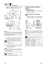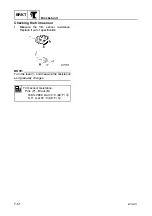
6C13G11
7-48
1
2
3
4
5
6
7
8
9
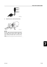
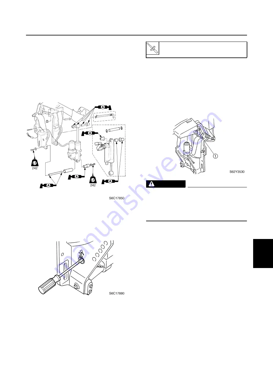
6.
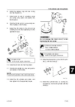
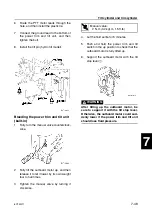
Route the PTT motor leads through the
hole, and then install the plastic tie.
7.
Connect the ground lead to the bottom of
the power trim and tilt unit, and then
tighten the bolt.
8.
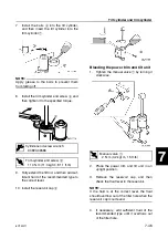
Install the tilt pin (hydro tilt model).
Bleeding the power trim and tilt unit
(built-in)
1.
Fully turn the manual valve counterclock-
wise.
2.
Fully tilt the outboard motor up, and then
release it to let it lower by its own weight
four to five times.
3.
Tighten the manual valve by turning it
clockwise.
4.
Let the fluid settle for 5 minutes.
5.
Push and hold the power trim and tilt
switch in the up position to check that the
outboard motor is fully tilted up.
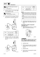
6.
Support the outboard motor with the tilt
stop lever
1
.
WARNING
After tilting up the outboard motor, be
sure to support it with the tilt stop lever.
Otherwise, the outboard motor could sud-
denly lower if the power trim and tilt unit
should lose fluid pressure.
T
R
.
.
Manual valve:
2 N·m (0.2 kgf·m, 1.5 ft·lb)
Содержание F50F
Страница 1: ...F50F FT50G F60C FT60D SERVICE MANUAL 6C1 28197 3G 11 290551 ...
Страница 4: ......
Страница 48: ...SPEC Specifications 2 25 6C13G11 MEMO ...
Страница 147: ...6C13G11 6 4 1 2 3 4 5 6 7 8 9 Ring nut wrench 3 90890 06511 Ring nut wrench extension 90890 06513 Special service tools ...
Страница 165: ...6C13G11 6 22 1 2 3 4 5 6 7 8 9 Shimming F50 F60 6 Drive shaft and lower case F50 F60 Shimming F50 F60 ...
Страница 190: ...LOWR Lower unit 6 47 6C13G11 Shimming FT50 FT60 6 ...
Страница 195: ...6C13G11 6 52 1 2 3 4 5 6 7 8 9 MEMO Backlash FT50 FT60 ...
Страница 221: ...6C13G11 7 24 1 2 3 4 5 6 7 8 9 Steering arm ...
Страница 249: ...6C13G11 7 52 1 2 3 4 5 6 7 8 9 MEMO Power trim and tilt electrical system ...
Страница 272: ...ELEC Electrical systems 8 21 6C13G11 MEMO ...
Страница 301: ...6C13G11 i 5 1 2 3 4 5 6 7 8 9 Index MEMO ...
Страница 303: ......
Страница 304: ...YAMAHA MOTOR CO LTD Printed in the Netherlands Jul 2004 1 2 1 CR E_2 ...

